
Distributed smart grid processing

a smart grid and distributed processing technology, applied in the field of distributed smart grid processing, can solve the problems of high processing cost, high processing cost, and high processing cost, and achieve the effect of improving processing efficiency, improving processing efficiency, and improving processing efficiency

Active Publication Date: 2015-09-10
ITRON NETWORKED SOLUTIONS INC
View PDF12 Cites 13 Cited by
  • Summary
  • Abstract
  • Description
  • Claims
  • Application Information

AI Technical Summary

Benefits of technology

The techniques set forth in this patent make it possible to perform complex network processing at the edges of the network (where data is collected) using a stream network. This approach allows for more efficient processing power and real-time data processing that is not possible with previous methods. The patent describes various embodiments, but notes that many modifications and variations will be possible without changing the scope and goal of the patent. Overall, the patent presents a way to effectively leverage network processing power and perform complex tasks in a distributed manner.

Problems solved by technology

One problem with approach described above is that, with the expansion of smart grid infrastructure, the amount of data that must be transmitted to the back office, stored in the database, and then processed, is growing quickly.
Consequently, the mesh network across which the smart meters transmit data may become over-burdened with traffic and, therefore, suffer from throughput issues.
In addition, the processing hardware implemented by the back office may quickly become obsolete as the amount of data that must be processed grows.
As a general matter, the infrastructure required to transport and process data generated by a smart grid cannot scale as quickly as the amount of data that is generated.

Method used


Image

  • Distributed smart grid processing
  • Distributed smart grid processing
  • Distributed smart grid processing

Examples


Embodiment Construction

[0024]In the following description, numerous specific details are set forth to provide a more thorough understanding of the present invention. However, it will be apparent to one of skill in the art that the present invention may be practiced without one or more of these specific details. In other instances, well-known features have not been described in order to avoid obscuring the present invention.

System Overview

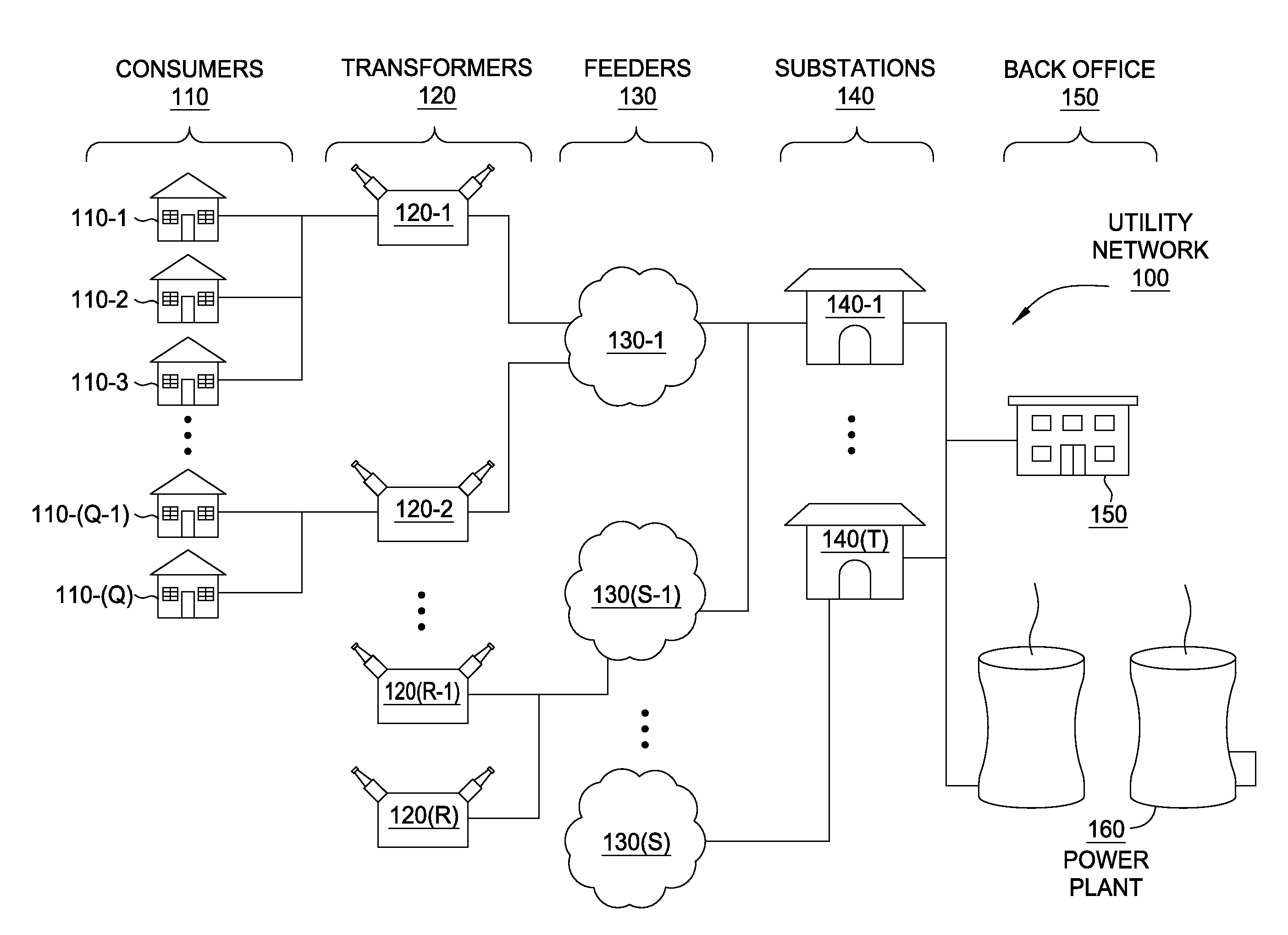
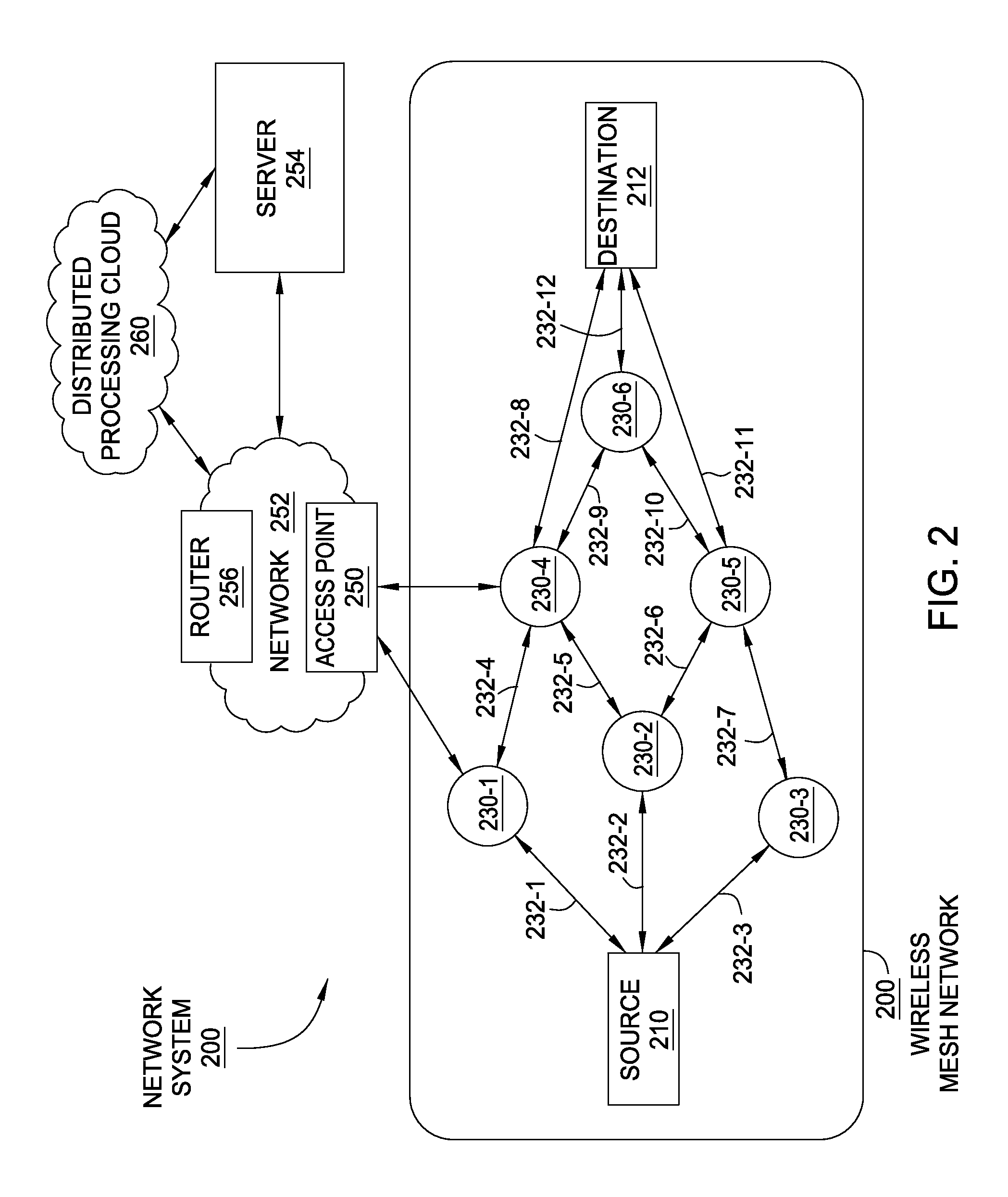
[0025]In the following disclosure, a multi-layered network architecture is described that includes a utility network, illustrated in FIG. 1, a wireless mesh network, illustrated in FIG. 2, and a stream network, illustrated in FIG. 5. The utility network includes hardware configured to transport and distribute electricity. The wireless mesh network includes hardware nodes residing within elements of that utility network, where those nodes are configured to execute firmware and / or software to (i) monitor the utility network and (ii) establish and maintain the wireless mesh ...


PUM


Abstract

Nodes within a wireless mesh network are configured to monitor time series data associated with a utility network, including voltage fluctuations, current levels, temperature data, humidity measurements, and other observable physical quantities. The nodes execute stream functions to process the recorded time series data and generate data streams. The node is configured to transmit generated data streams to neighboring nodes. A neighboring node may execute other stream functions to process the received data stream(s), thereby generating additional data streams. A server coupled to the wireless mesh network collects and processes the data streams to identify events occurring within the network.

Description

CROSS-REFERENCE TO RELATED APPLICATIONS[0001]This application claims the benefit of United States provisional patent application titled “Smart Grid Processing to Evaluate Grid Conditions,” filed on Mar. 10, 2014, and having Ser. No. 61 / 950,425, United States provisional patent application titled “Distributed Smart Grid Processing,” filed on Sep. 3, 2014 and having Ser. No. 62 / 045,423, and United States provisional patent application titled “Distributed Smart Grid Processing,” filed on Dec. 19, 2014 and having Ser. No. 62 / 094,907. The subject matter of each of these related applications is hereby incorporated by reference.BACKGROUND OF THE INVENTION[0002]1. Field of the Invention[0003]Embodiments of the present invention relate generally to network architecture and semantics for distributed processing on a data pipeline, and, more specifically, to distributed smart grid processing.[0004]2. Description of the Related Art[0005]A conventional electricity distribution infrastructure typi...

Claims


Application Information

Patent Timeline
IPC IPC(8): H02J3/24H04L29/08H04L12/26
CPCH02J3/24H04L67/16H04L43/04H04L67/125H04L69/28H02J3/06Y04S40/126Y04S40/18H02J2203/20H02J13/00017H02J13/00024H02J13/00034Y02E60/00Y04S40/00Y04S40/20Y04S40/124H02J13/00022H04L67/51H02J3/00G01R25/00G01R21/00H04L41/12H02J3/007H04L41/0803H04L43/0888H04L41/0896H04L43/0876
Inventor SUM, CHARLES P.FLAMMER, III, GEORGE H.
Owner ITRON NETWORKED SOLUTIONS INC
Learn More