Polarization image processing apparatus
a technology of image processing and polarization, applied in the direction of color signal processing circuit, vehicle cleaning, instruments, etc., can solve the problem of difficult to detect raindrops on the basis of color and brightness of objects
- Summary
- Abstract
- Description
- Claims
- Application Information
AI Technical Summary
Benefits of technology
Problems solved by technology
Method used
Image
Examples
first embodiment
Modification of First Embodiment
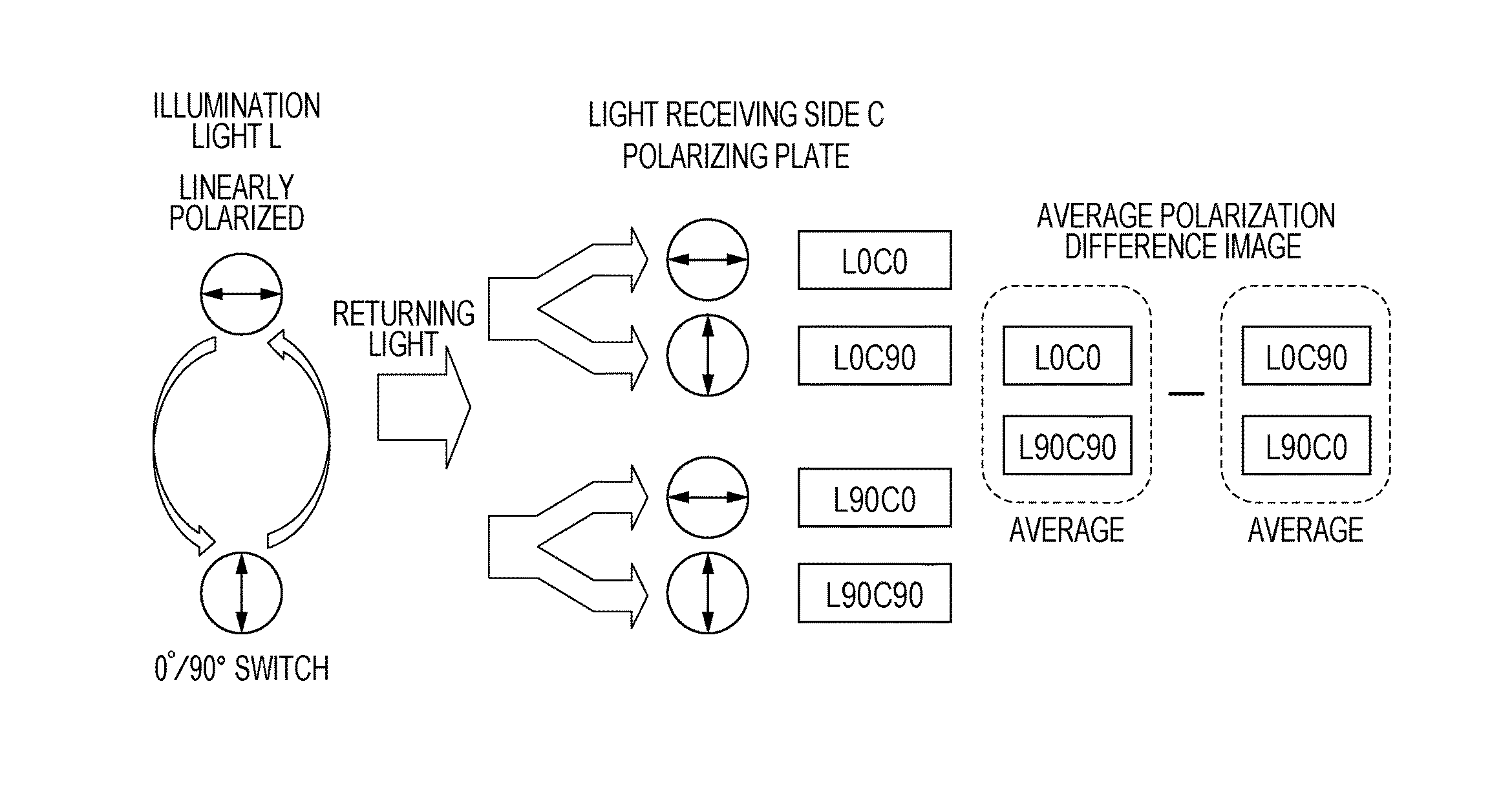
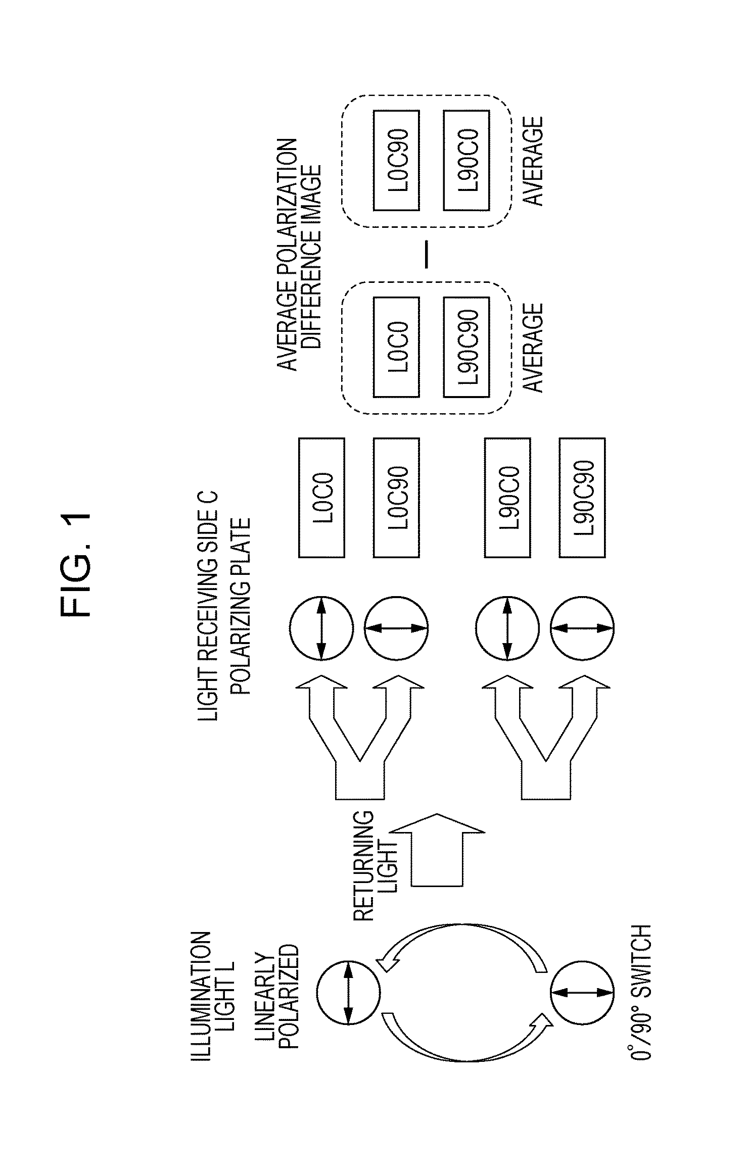
[0146]FIG. 12 illustrates a modification of the first embodiment of the present disclosure. In the embodiment described with reference to FIG. 1, the polarizing plates at the light receiving side C have transmission axes in two directions: 0° and 90°. This modification differs from the embodiment illustrated in FIG. 1 in that polarizing plates at the light receiving side C have transmission axes in three directions: 0°, 45°, and 90°. In other words, in the embodiment illustrated in FIG. 1, images L0C0 and L90C90 obtained while the polarizing directions (transmission axis directions) of the polarizing plates of the imaging systems are parallel to the polarizing direction of the illumination light are used as the parallel-Nicols images. In contrast, in the present modification, images L0C45 and L90C45 obtained while the polarizing directions of the polarizing plates are at an angle of 45° with respect to the polarizing direction of the illumination ligh...
second embodiment
[0159]FIG. 15 illustrates a polarization imaging method according to a second embodiment of the present disclosure. In the present embodiment, circularly polarized light is used as illumination light instead of linearly polarized light. By using circularly polarized light, raindrops can be can be evenly detected irrespective of the polarization characteristics in a certain direction on the object surface.
[0160]In the present embodiment, an object is illuminated with illumination light L, which is circularly polarized light having an electric field oscillation plane that temporally alternately rotates clockwise and counterclockwise on a plane perpendicular to the travelling direction of the light. Although the direction of circular polarization is normally defined as a direction when viewed in the light travelling direction, in this embodiment, the direction of circular polarization is always defined as a direction when viewed from the camera. In this coordinate system, the direction...
third embodiment
[0168]FIG. 19 illustrates an imaging method according to a third embodiment of the present disclosure. Similar to the second embodiment, in the present embodiment, circularly polarized light is used as illumination light. The third embodiment differs from the second embodiment in that only circularly polarized light having a single polarization direction is used as illumination light. Accordingly, the structure of the illumination unit can be simplified, and raindrops can be evenly detected irrespective of the polarization characteristics in a certain direction on the object surface.
[0169]An object is illuminated with illumination light L, which is circularly polarized light having an oscillation plane that rotates clockwise or counterclockwise on a plane perpendicular to the travelling direction of the light. Although the direction of circular polarization is not limited, here, it is assumed that the direction of circular polarization is clockwise when viewed from the camera.
[0170]...
PUM
 Abstract
Description
Claims
Application Information
 - R&D
- Intellectual Property
- Life Sciences
- Materials
- Tech Scout
- Unparalleled Data Quality
- Higher Quality Content
- 60% Fewer Hallucinations
Browse by: Latest US Patents, China's latest patents, Technical Efficacy Thesaurus, Application Domain, Technology Topic, Popular Technical Reports.
© 2025 PatSnap. All rights reserved.Legal|Privacy policy|Modern Slavery Act Transparency Statement|Sitemap|About US| Contact US: help@patsnap.com


