
Ac-powered LED light engines, integrated circuits and illuminating apparatuses having the same

a led light engine and led light technology, applied in the direction of electroluminescent light sources, electric lighting sources, semiconductor lamp usage, etc., can solve the problems of emi filter, flicker phenomenon, and need for a more complicated and expensive driving circui

Inactive Publication Date: 2015-09-10
GRP TECH
View PDF1 Cites 26 Cited by
  • Summary
  • Abstract
  • Description
  • Claims
  • Application Information

AI Technical Summary

Benefits of technology

The present invention is about an LED light engine that can adjust the number and current of LED sub-arrays based on the voltage level of the input voltage. This allows for dimming without affecting the high PF (Peak Factor) and low THD (Total Harmonic Distortion) performance. The invention also suggests using a shared current sensing and modulation unit to dim the extrinsic LED sub-arrays. Additionally, the invention explores the possibility of integrating the LED light engine into an integrated circuit to reduce the number of parts and manufacturing costs.

Problems solved by technology

The first problem would be the need for a more complicated and more expensive driving circuit consisting of an EMI filter, a bridge rectifier, a short-life Power Factor Corrector (PFC), etc. to drive LEDs.
The second problem would be the flicker phenomenon due to no current flow through the LEDs during the dead time.
The third problem would be a lower power factor exhibited by a low-power PFC with a loop current too weak to be precisely sensed to correctly shape the AC input current into a sinusoidal waveform.
Besides, traditional phase-cut dimming, be it leading-edge or trailing-edge TRIAC dimming, would achieve dimming function by means of cutting off some conducting phase from the line current waveform, leading to significant deterioration of PF and THD.

Method used


Image

  • Ac-powered LED light engines, integrated circuits and illuminating apparatuses having the same
  • Ac-powered LED light engines, integrated circuits and illuminating apparatuses having the same
  • Ac-powered LED light engines, integrated circuits and illuminating apparatuses having the same

Examples


Embodiment Construction

[0021]The detailed explanation of the present invention is described as follows. The preferred embodiments are presented for purposes of illustrations and description, and not intended to limit the spirit and scope of the present invention.

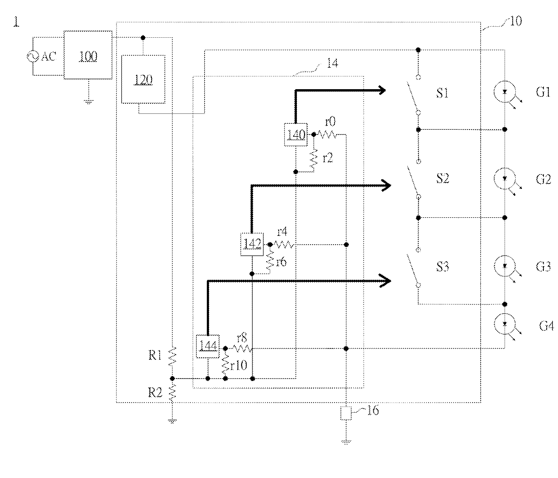
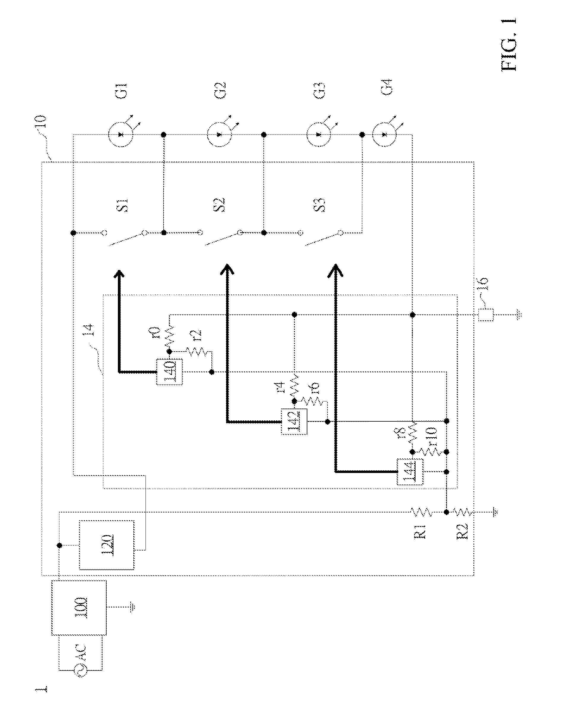
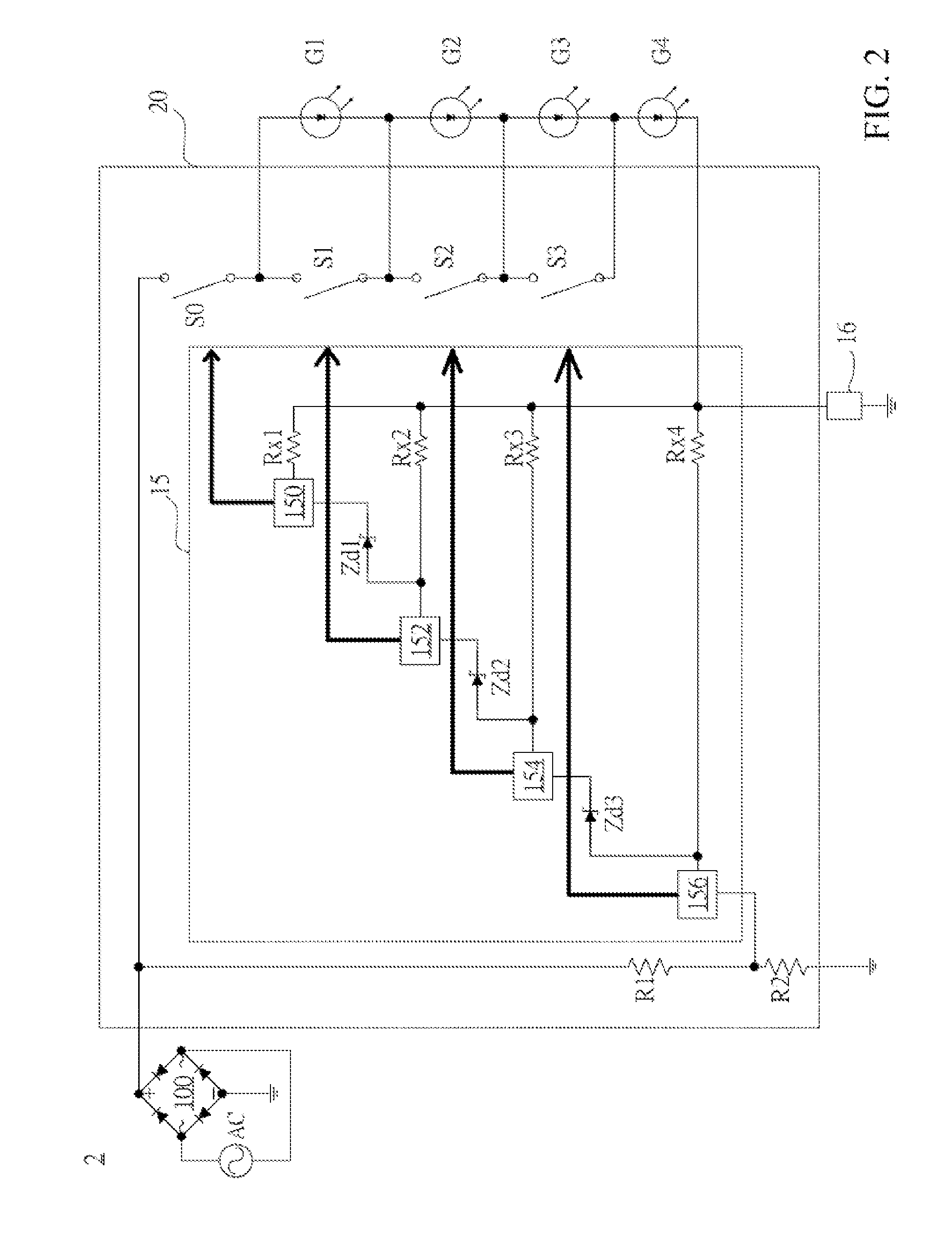
[0022]FIG. 1 illustrates a block diagram of an illuminating apparatus 1 equipped with an AC-powered LED light engine 10 designed to gear up from the bottom up and gear down from the top down the extrinsic LED sub-arrays (G1, G2, G3, and G4) in accordance with an embodiment of the present invention. The illuminating apparatus 1 comprises a rectifier 100 coupled to an AC mains, an AC-powered LED light engine 10, and a shared current sense and modulation unit 16, and is loaded up with a plurality of extrinsic LED sub-arrays (G1, G2, G3, and G4).

[0023]The AC-powered LED light engine 10 is coupled between the rectifier 100 and the extrinsic LED sub-arrays (G1, G2, G3, and G4), and has a normally closed current regulator 120 coupled to the rectifier 100...


PUM


Abstract

Disclosed are novel AC-powered LED light engines for Solid State Lighting (SSL) able to achieve a high PF and a low THD without a traditional PFC. Getting rid of bulky, and costly magnetic components, short-life electrolytic capacitor, and EMI-causing fast switching, the disclosed AC-powered LED light engines ushers in a cost-effective, and energy-efficient LED driver design while eliminating the short-life electrolytic capacitor in an LED driver and reducing the Total Cost of Ownership (TOC). Thanks to no bulky components, the disclosed AC-powered LED light engines in a discrete or an integrated circuit form could be applied to the increasingly popular Driver-on-Board (DoB) design. Aside from being TRIAC-dimmable via legacy phase-cut dimmers, the disclosed LED light engines could also be made PWM-, analog-, or rheostat-dimmable with the incorporation of an appropriate dimming circuit to modulate the average LED current, adding more flexibility and versatility to dimming applications.

Description

CROSS-REFERENCE TO RELATED APPLICATIONS[0001]This application claims the benefits of TW 103107793, filed Mar. 7, 2014, and TW 103124262, filed Jul. 15, 2014, both of which are fully incorporated herein by reference.BACKGROUND OF THE INVENTION[0002]1. Field of the Invention[0003]The present invention relates to an AC-powered LED light engine able to gradually gear up and down the number and current of excited LED sub-arrays in accordance with the voltage level of the rectified sinusoidal input voltage, and able to smoothly dim up and down the extrinsic LED sub-arrays via a shared current sense and modulation unit while keeping the quasi-sinusoidal line current waveform in good shape as well as maintaining almost the same high Power Factor (PF) and almost the same low Total Harmonic Distortion (THD) throughout the entire dimming range.[0004]2. Description of the Prior Art[0005]LED-based lighting devices are gradually becoming the preferred lighting equipment because of having a longer...

Claims


Application Information

Patent Timeline
IPC IPC(8): H05B33/08H05B44/00
CPCH05B33/0827H05B33/0809H05B33/0845H05B45/10H05B45/48H05B45/395Y02B20/30H05B45/46
Inventor YU, CHING SHENGWANG, CHIH LIANGCHEN, KUANG HUI
Owner GRP TECH
Learn More