
Wind turbine inertia control system

a control system and wind turbine technology, applied in the direction of electric generator control, machines/engines, mechanical equipment, etc., can solve the problems of grid frequency suddenly changing beyond its nominal value, grid operators increasingly toughening wind turbine-to-grid coupling conditions, and not allowing a return to the nominal frequency

Active Publication Date: 2015-09-17
GAMESA INNOVATION & TECH SA
View PDF29 Cites 22 Cited by
  • Summary
  • Abstract
  • Description
  • Claims
  • Application Information

AI Technical Summary

Benefits of technology

This patent is about a method that can mimic a synchronous generator in terms of its inertial response. To achieve this, a specific controller is utilized. The method helps to solve issues with wind turbine grid uncoupling and electronic converters, which are currently present in the state of the art. The technical benefit of this patent is the improved performance of wind turbines in terms of inertial response.

Problems solved by technology

At present, the impact of connecting wind turbines to the electricity grid is inevitable and thus grid operators are increasingly toughening wind turbine-to-grid coupling conditions.
Transmission system operators are particularly concerned with frequency transients, normally arising when disconnecting the generator, loads or even a part of the transmission system, and consequently causing the grid frequency to change suddenly beyond its nominal values because of the difference between produced active power and consumed active power.
However, this response, known as primary response, does not permit a return to the nominal frequency.
However, variable speed wind turbines do not have this “natural” response (inertial response) to grid frequency changes because electronic converter controllers uncouple the frequency from the generator rotational speed.
Therefore, wind turbines do not naturally reduce their speed in relation to the frequency and do not deliver this energy by moving the rotor.
Variable speed wind turbines do not buffer frequency drops / spikes.
Given that wind power is becoming an essential part of the electricity system, an incapacity to provide inertial response results in a reduction of the inertia in the system and, consequently, an increase in frequency drops / spikes.
Accordingly, measures must be taken to prevent the wind turbines' lack of inertial response, which could entail major problems in the electricity grid caused by frequency drops / spikes.
Nevertheless, the power feed falls quickly thereafter.
In grid terms, this is known as a “recovery period” after feeding the inertia, and it entails wind turbine performance uncertainties to the wind farm insofar as frequency response and could even cause an undesired drop in frequency after the inertial response.
This provokes a drastic drop in production, which remains until the wind turbine recovers its initial speed.
However, when this extra power ends, the wind turbine should return to its normal operating mode, resulting in the ensuing “recovery period”, which could cause an undesired frequency drop after this inertial response.
This “recovery period” is a challenge facing the grid because, during the delivery of the inertial response, the grid is supported and the grid frequency change is buffered; thus the wind farm is helping the system through this situation.
Nevertheless, when the recovery period commences, wind farm production drops below the values before the event and, consequently, during this period of time, the wind farm could cause a grid frequency drop that must be solved by another generation plant.

Method used


Image

  • Wind turbine inertia control system
  • Wind turbine inertia control system
  • Wind turbine inertia control system

Examples


Embodiment Construction

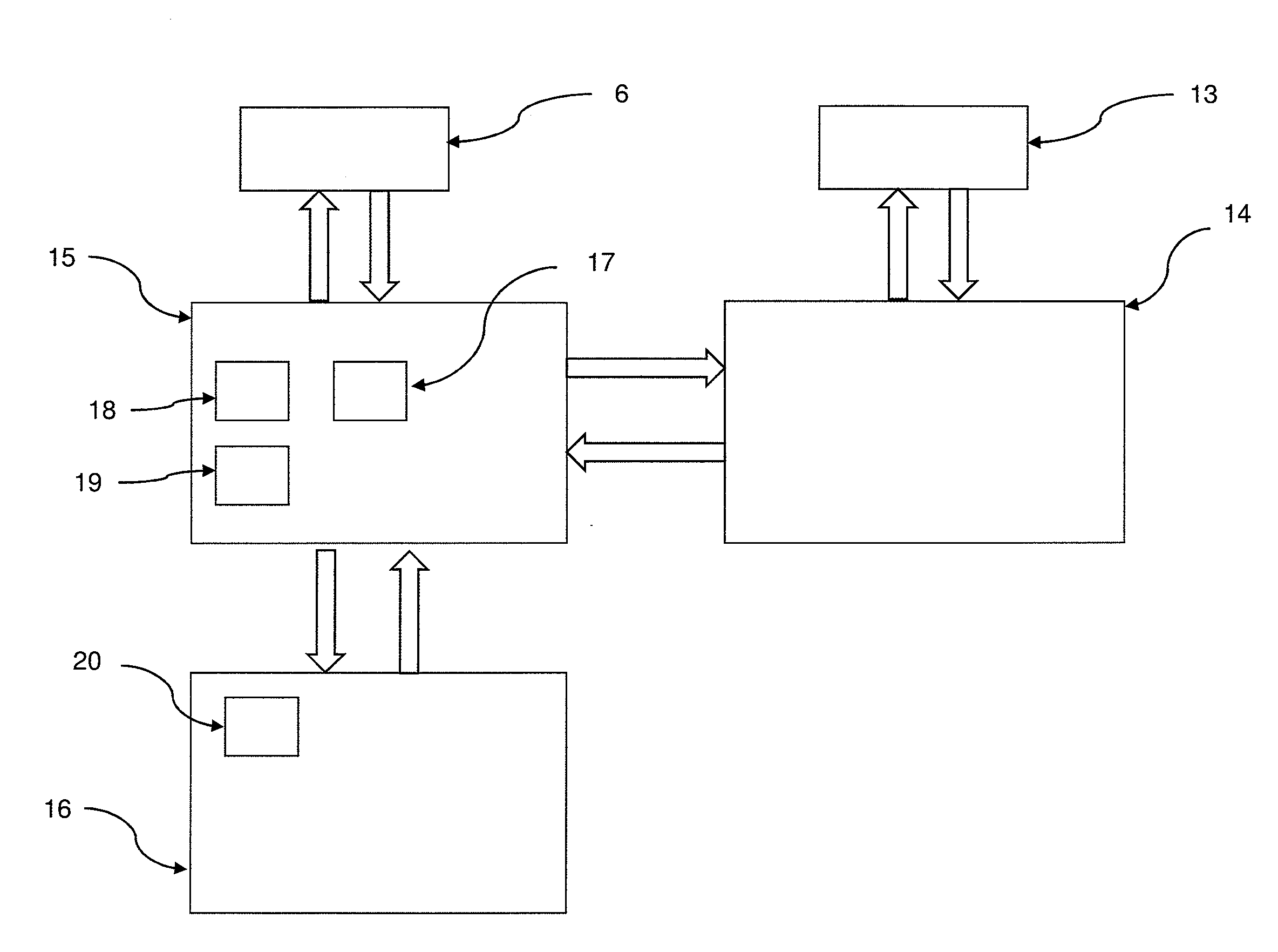
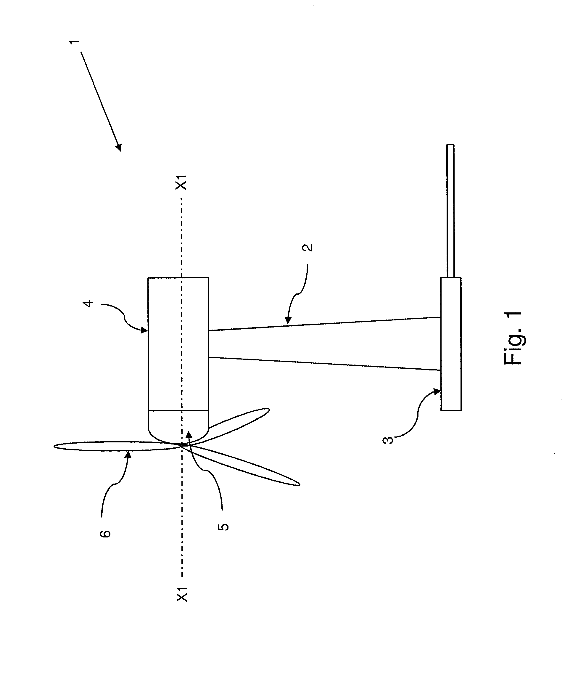
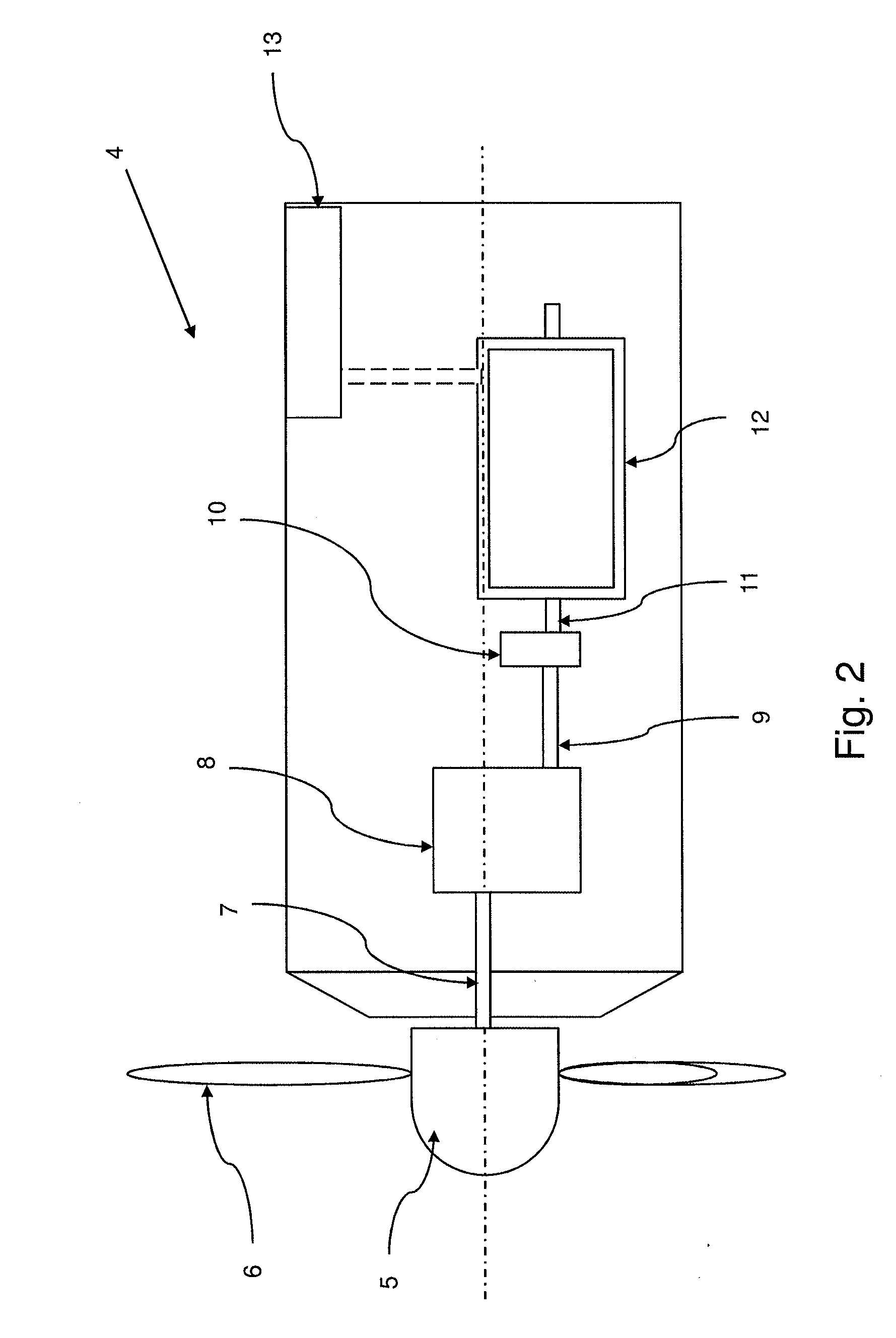
[0017]One object of the invention is a wind turbine comprising a rotor, which drives a generator that interacts with a power converter to generate electricity; a wind turbine controller equipped with a blade pitch angle controller for at least one blade and a generated power controller, a power converter controller, which interacts with the wind turbine controller; and a regulation system that forestalls interruptions in the active power output after the addition or subtraction of power proportional to the frequency change rate by generating a power signal, negatively proportional to the frequency change rate, which is then added to the generated power controller power reference of the wind turbine controller so that the rotational speed reference of the controller is adapted according to the grid frequency

[0018]An object of the invention is a method that emulates the same performance as a synchronous generator insofar as inertial response. For this purpose, the implementation of a ...


PUM


Abstract

Inertia control system for a wind turbine comprising a rotor (5), generator (12) driven by the rotor (5) that interacts with a power converter (13) to generate electricity, a wind turbine controller (15) that comprises a blade pitch controller (19) and a generated power controller (18), a controller for the power converter (14) that interacts with the wind turbine controller (15), characterized because it comprises an inertia emulation block (17) that generates an extra power signal (32) negatively proportional to the frequency change rate (23) that is added to the power reference of the wind turbine generated power controller (15) and adapts the rotational speed reference of the wind turbine controller (15) according to the grid frequency (21) to prevent distortion in the active power output after adding or subtracting power in proportion to the frequency change rate (23).

Description

FIELD OF THE INVENTION[0001]The present invention concerns the control over the feed of power from wind farms into the electricity grid and, more specifically, to an inertia control system for a wind farm that comprises an inertia controller to define and communicate references to the wind turbines constituting the wind farm, and to provide the value of an inertia constant that can be configured in the wind farm wind turbines.BACKGROUND OF THE INVENTION[0002]Wind turbines convert the kinetic energy of the wind into electricity, which is then transmitted to a substation in the wind turbine wind farm. This wind turbine wind farm has at least one wind farm controller and at least one wind turbine comprising a rotor, which drives a generator that interacts with a power converter to generate electricity; a wind turbine controller equipped with a blade pitch angle controller and a generated power controller, a power converter controller, which interacts with the wind turbine controller; a...

Claims


Application Information

Patent Timeline
Patent Type & Authority Applications(United States)
IPC IPC(8): F03D7/02F03D9/00
CPCF03D7/0284F03D9/005F03D7/0276H02P9/00F05B2270/1033F05B2270/107F05B2270/337H02P21/143F03D9/257H02J2300/28H02J3/381Y02E10/72Y02E10/76H02J3/48F03D9/255F03D7/042F03D80/88
Inventor JIMENEZ BUENDIA, FRANCISCO
Owner GAMESA INNOVATION & TECH SA
Learn More