Detection scheme for particle size and concentration measurement

Inactive Publication Date: 2015-09-17
PARTICLE MEASURING SYST
View PDF3 Cites 13 Cited by
  • Summary
  • Abstract
  • Description
  • Claims
  • Application Information

AI Technical Summary

Benefits of technology

The present invention introduces new detection schemes that have several advantages. These include higher sensitivity, the ability to measure higher particle concentration, the ability to characterize particles, the ability to measure fluorescence from particles, and the ability to measure particle's velocity. Additionally, these schemes offer the advantage of not requiring any moving parts to scan the beam, which makes the system more robust and reliable. Overall, the invention offers a more efficient and effective way to detect and characterize particles in flow.

Problems solved by technology

Especially when approaching the particle size range around 1 micron and below, most of these techniques suffer from inaccuracies due to the effect of the real and imaginary part of the particle's refractive index.
In this technique the interaction of a scanning, focused laser beam and the particles is analyzed in the time domain rather than in the amplitude domain, resulting in lower sensitivity to variation in the refractive index.
Thus if the TOT technique is targeted to resolve and measure particles in the micron and sub-micron range it would be limited in its ability to measure low concentrations as the instantaneous focus volume is small and the interaction rate of particles is low.
On the other hand, taking a larger spot will improve the concentration measurement rate but will degrade the quality and resolution of the size analysis.

Method used


Image

  • Detection scheme for particle size and concentration measurement
  • Detection scheme for particle size and concentration measurement
  • Detection scheme for particle size and concentration measurement

Examples


Embodiment Construction

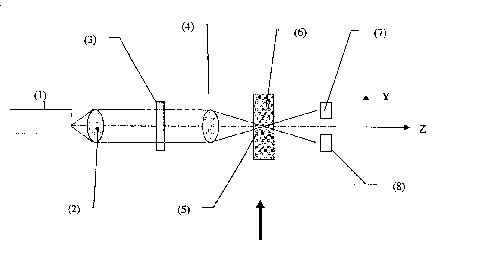
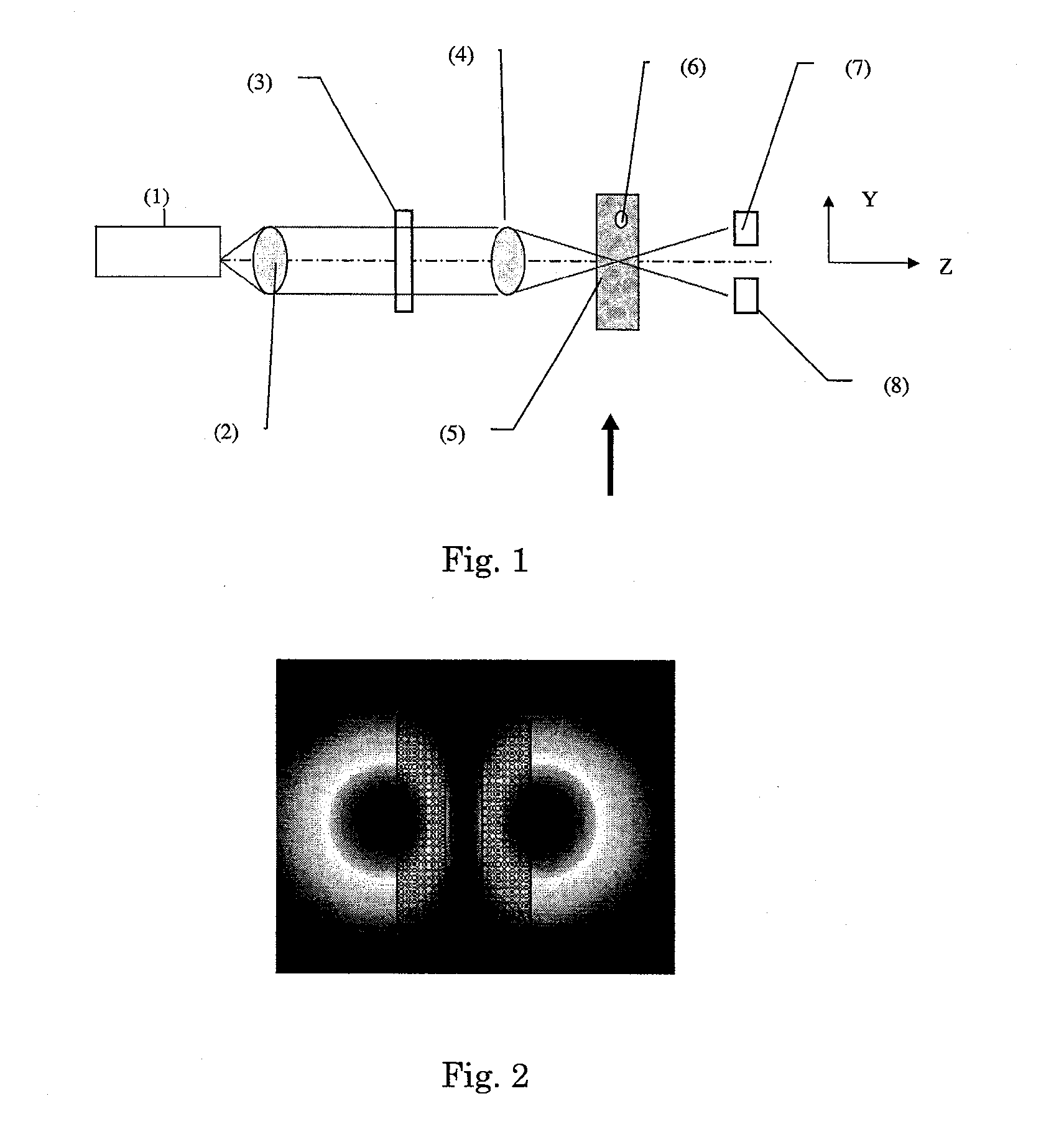
[0039]FIG. 1 schematically shows an embodiment of a particle monitoring system. The system shown in FIG. 1 comprises a laser (1), which generates a Gaussian beam; collimating lens (2); phase mask (3), which converts the Gaussian laser beam into a structured dark beam; a focusing lens (4), which focuses the dark beam inside a cuvette (5) through which water containing particles (6) flows in the direction of the arrow; and two detectors (7) and (8). It is noted that in the case of airborne particles, the air stream bearing the particles need not be confined within a cuvette. The positioning of the detectors with respect to the illuminating dark beam pattern is shown in FIG. 2. In this embodiment one detector is positioned over each intensity lobe of the original dark beam. As particles cross the beam the output intensity pattern is modified and the detectors sense the change. The detector spacing can be optimized for sensitivity by aligning it to the maximum intensity gradient of the ...


PUM


Abstract

The present invention provides a system and method of particle size and concentration measurement that comprises the steps of: providing a focused, synthesized, structured laser beam, causing the beam to interact with the particles, measuring the interaction signal and the number of interactions per unit time of the beam with the particles, and using algorithms to map the interaction signals to the particle size and the number of interactions per unit time to the concentration.

Description

FIELD OF THE INVENTION[0001]The present invention is related to the field of measuring particle size and concentration. More specifically it relates to the use of optical methods for measuring particle size and concentration.BACKGROUND OF THE INVENTION[0002]Many techniques exist for particle size and concentration analysis (PSA), they can be reviewed for reference in the book by Terry Alan “Introduction to Particle Size Analysis” T. Allen, Particle size analysis John Wiley & Sons; ISBN: 0471262218; June, 1983. The most commonly used techniques are optical, based on the interaction of the measured particles with laser radiation. Especially when approaching the particle size range around 1 micron and below, most of these techniques suffer from inaccuracies due to the effect of the real and imaginary part of the particle's refractive index. It is known, for example, that in some techniques, such as techniques based on Fraunhoffer diffraction analysis, light absorbing particles would be...

Claims


Application Information

Patent Timeline
IPC IPC(8): G01N15/02G01N15/06
CPCG01N15/0205G01N2015/0693G01N15/06G01N2015/145G01N15/1434G01N15/1436G01N2015/1454G01N15/1459G01N15/075G01N15/1456
Inventor SHAMIR, JOSEPH
Owner PARTICLE MEASURING SYST
Why Eureka
Try Eureka