Cutting method

a cutting method and cutting technology, applied in the field of cutting methods, can solve the problems of difficult to completely remove the burrs generated by cutting, and achieve the effects of reducing ductility, reducing the generation of burrs, and reducing the production cos

Active Publication Date: 2015-09-17
DISCO CORP
View PDF4 Cites 36 Cited by
  • Summary
  • Abstract
  • Description
  • Claims
  • Application Information

AI Technical Summary

Benefits of technology

[0011]In the cutting method of the present invention, cutting is carried out while supplying the cutting fluid containing an organic acid and an oxidizing agent to the processing point. By the organic acid contained in the cutting fluid, the metal is modified to be lowered in ductility, resulting in that generation of burrs is restrained. Besides, wi

Problems solved by technology

By the conventional methods, however, it is very difficult to

Method used


Image

  • Cutting method
  • Cutting method
  • Cutting method

Examples


Embodiment Construction

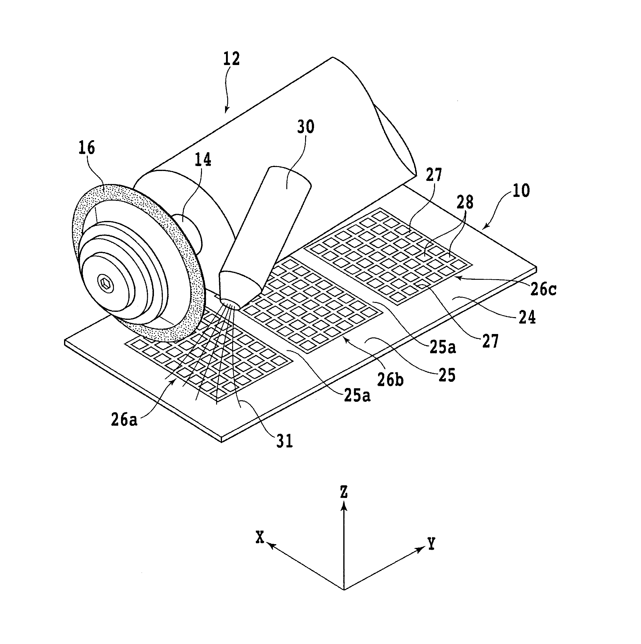
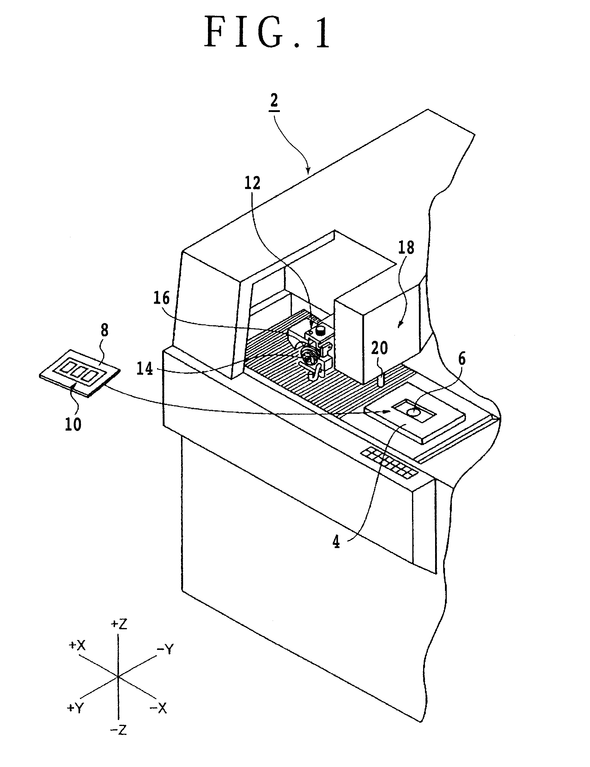
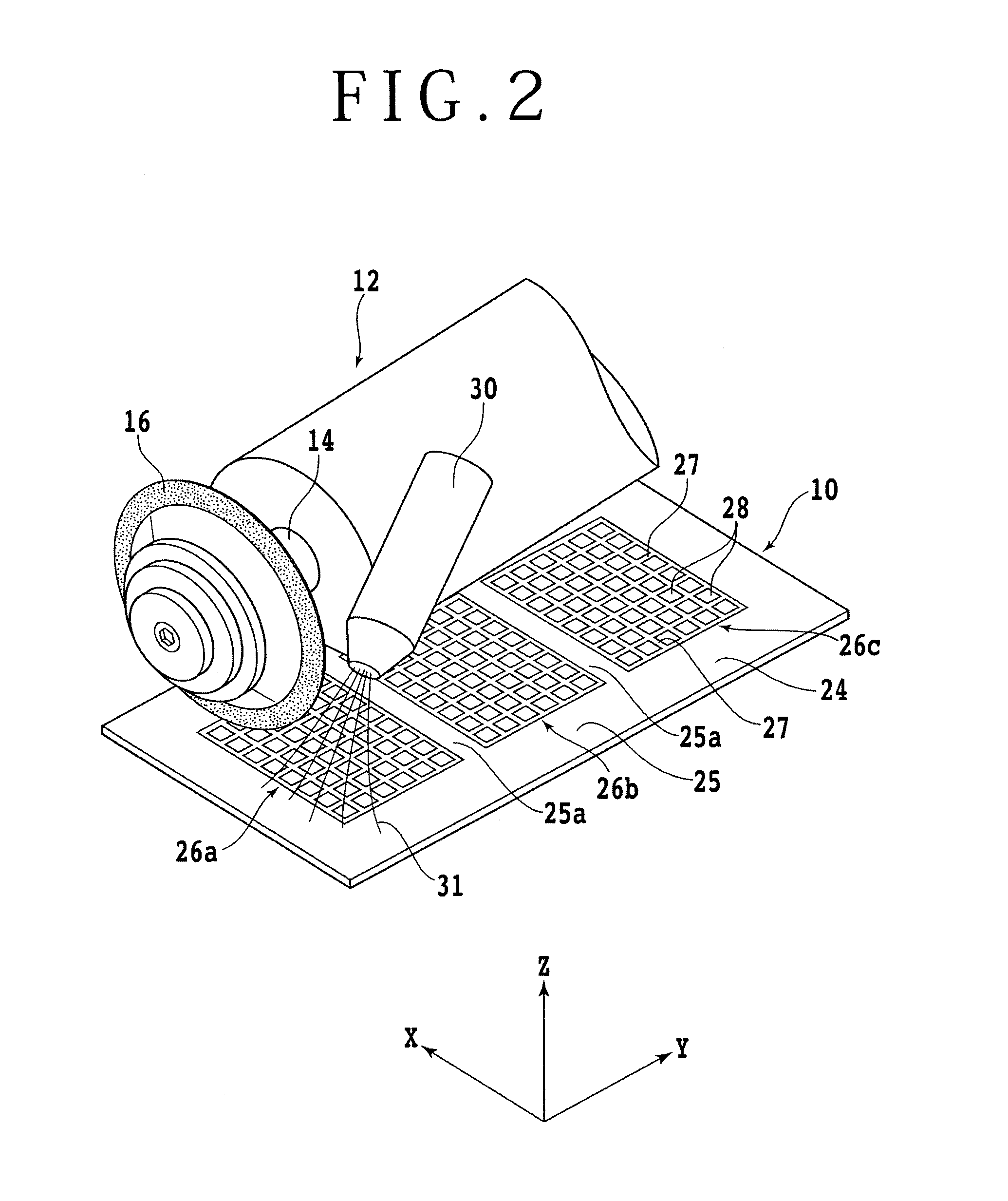
[0017]An embodiment of the present invention will be described in detail below. Referring to FIG. 1, there is shown a partially broken perspective view of a cutting apparatus 2 suitable for carrying out the cutting method of the present invention. A suction table 4 of the cutting apparatus 2 is formed with a suction part 6 which communicates with a suction source (not shown). The suction table 4 is so arranged that it can be reciprocated in an X-axis direction and can be rotated. A QFN substrate 10, which is a kind of package substrate and is a workpiece here, is placed on a fixing jig (holding jig) 8. The fixing jig 8 with the QFN substrate 10 mounted thereon is placed on the suction table 4 of the cutting apparatus 2. When the fixing jig 8 carrying the QFN substrate 10 thereon is mounted on the suction table 4 and a suction force is applied through the suction part 6, the suction force acts on each of suction holes (not shown) of the fixing jig 8, whereby the QFN substrate 10 is h...


PUM


Abstract

A cutting method for cutting by a cutting blade a workpiece which includes metal at least in a predetermined cutting position. The cutting method includes a cutting step of cutting by the cutting blade the predetermined cutting position of the workpiece while supplying a cutting fluid, containing an organic acid and an oxidizing agent, to a processing point at which the cutting blade cuts into the workpiece.

Description

BACKGROUND OF THE INVENTION[0001]1. Field of the Invention[0002]The present invention relates to a cutting method suitable for cutting a QFN substrate, a wafer having TEG formed on predetermined division lines, or the like.[0003]2. Description of the Related Art[0004]In recent years, there has been a demand for more weight reductions and miniaturization in regard of such electrical apparatuses as cell phones and personal computers. As a device suited to the miniaturization, a technology called chip size package (CSP) has been developed and put to practical use in which a semiconductor chip is packaged to form a device. CSPs are formed, for example, by dividing a quad flat non-lead package (QFN) substrate into individual devices. A QFN substrate includes a plurality of semiconductor chips arranged at predetermined intervals, an electrode frame formed in a grid pattern so as to partition the semiconductor chips, electrode terminals arranged to extend like fishbone inward from the elec...

Claims


Application Information

Patent Timeline
IPC IPC(8): H01L21/78
CPCH01L21/78H01L21/3043B28D5/022B28D5/047H01L21/67092
Inventor TAKENOUCHI, KENJI
Owner DISCO CORP
Why Eureka
Try Eureka