
Power supply arrangement of a wind farm

a technology of wind farm and power supply arrangement, which is applied in the direction of emergency power supply arrangement, electric generator control, greenhouse gas reduction, etc., can solve the problems of increasing the cost of the wind farm. , to achieve the effect of more economical

Active Publication Date: 2015-09-17
SIEMENS ENERGY GLOBAL GMBH & CO KG
View PDF16 Cites 20 Cited by
  • Summary
  • Abstract
  • Description
  • Claims
  • Application Information

AI Technical Summary

Benefits of technology

The invention provides an auxiliary power supply arrangement for wind farms that can be supplemented as necessary by a DC voltage from the utility grid. This arrangement ensures that sufficient power is always available to maintain backup power to the wind turbines and to re-start them after a wind farm downtime. The wind farm can resume outputting its rated power more quickly. The method is straightforward and economical, and can be used in conjunction with existing onshore facilities. The auxiliary power supply arrangement includes an AC battery charger to maintain charge in the batteries during an uptime of the wind farm. The power converter of the auxiliary power supply arrangement can be used to control the offshore AC voltage, and a backfeed switch is used to prevent damage to components of the auxiliary power supply from overvoltage.

Problems solved by technology

Electricity can be transported as alternating current (AC), but AC transport is generally associated with losses, particularly over long distances.
However, such a bi-directional offshore power converter is expensive and adds considerably to the cost of the wind park.
Clearly, such an additional transmission link also adds considerably to the overall cost of the windfarm.
Since future HVDC-connected wind farms will often be located 100-200 km from the shore, such an additional AC subsea cable connection presents a severe challenge economically as well as technically.

Method used


Image

  • Power supply arrangement of a wind farm
  • Power supply arrangement of a wind farm
  • Power supply arrangement of a wind farm

Examples


Embodiment Construction

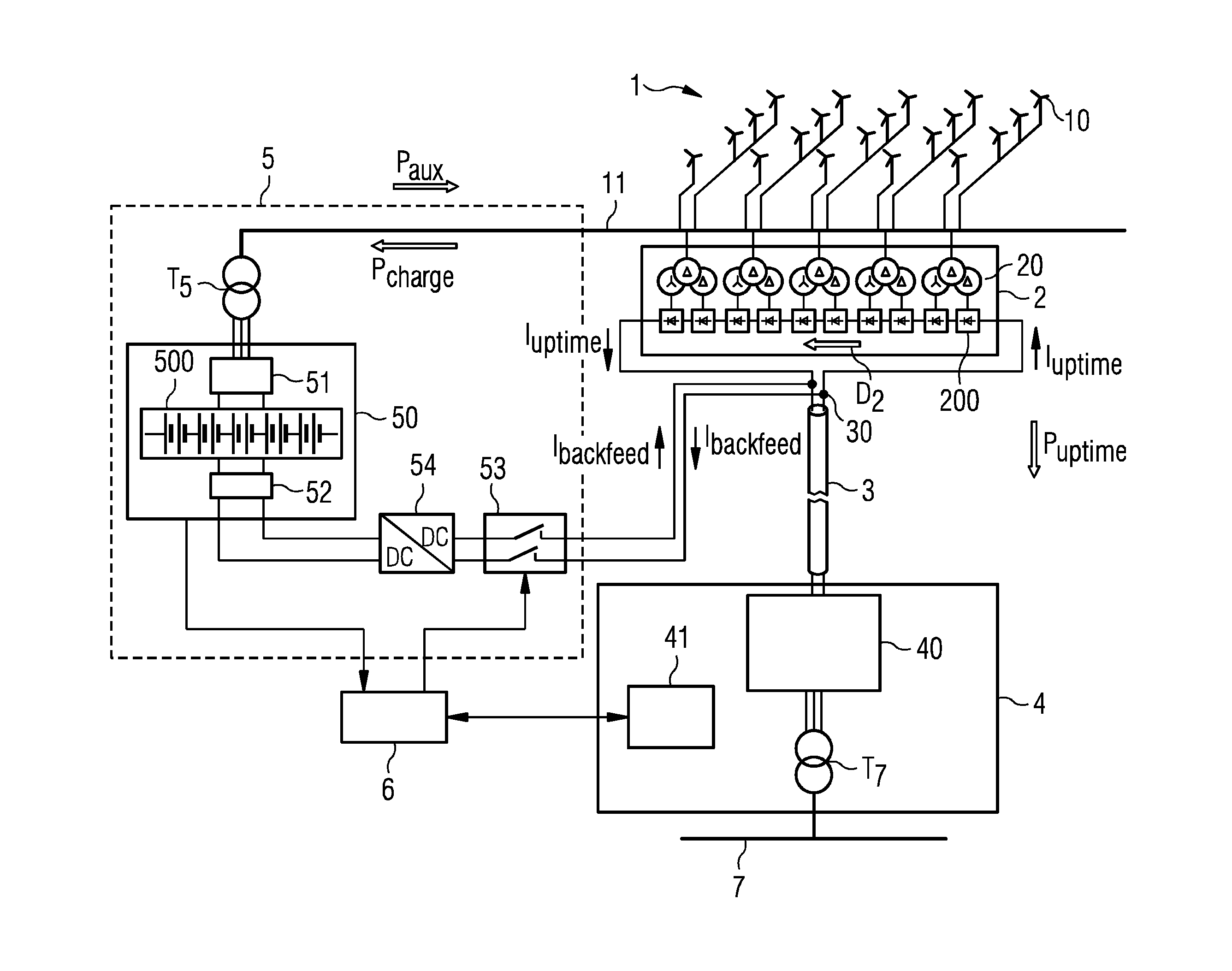
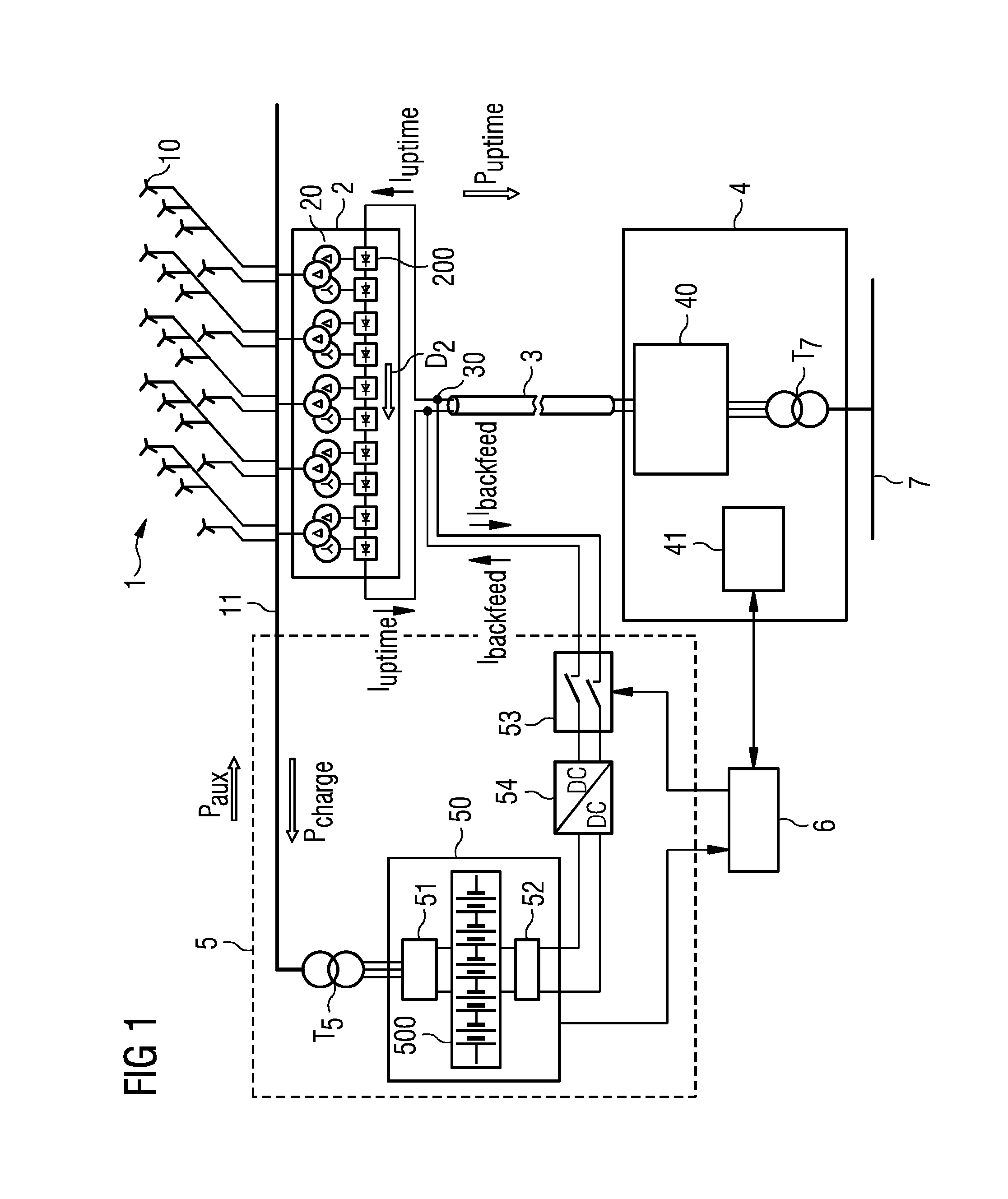
[0032]FIG. 1 is a schematic representation of a wind farm 1 comprising an auxiliary power supply arrangement 5 according to an embodiment of the invention. Here, the wind farm 1 is an offshore wind farm 1 comprising a plurality of wind turbines 10 that generate three-phase AC electricity. The AC power output from the wind turbines 10 is transformed by passive rectifiers 200 of an AC / DC converter 20 of an offshore substation 2 into DC power for transport over a HVDC transmission link 3 to an onshore substation 4. In this embodiment, the AC / DC converter 20 of the offshore substation 2 allows current flow in one direction D2 only. DC current Iuptime flows in a closed loop from the onshore converter 4 through the offshore converter 2 and back to the onshore converter 4. Conversion from DC back to AC is performed by a full-bridge converter 40 of the onshore substation 4 so that the power Puptime can be fed into a utility grid 7. The offshore components 1, 2 are spatially separate from th...


PUM


Abstract

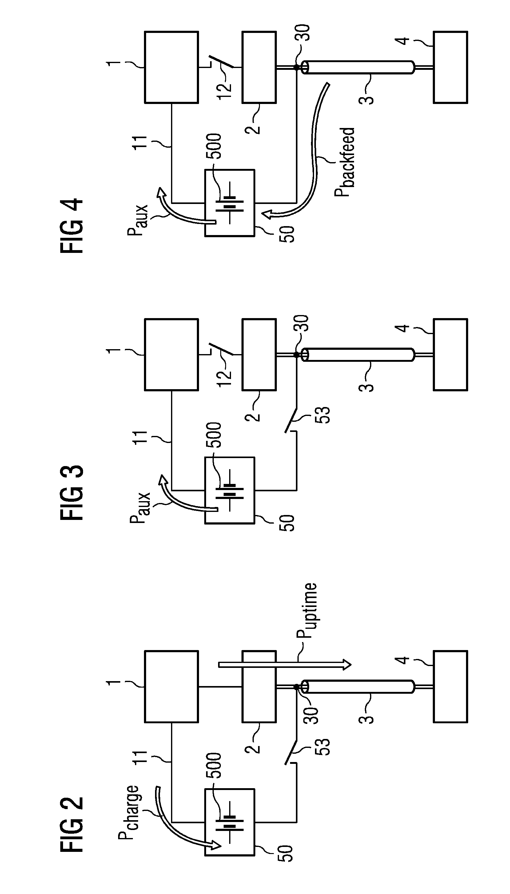
A power supply arrangement adapted to provide auxiliary power to a wind farm that feeds into a HVDC transmission link is provided. The power supply arrangement has an auxiliary power supply to deliver auxiliary power (Paux) to the wind farm; a backfeed control for initiating provision of a backfeed voltage on the HVDC link during a wind farm downtime; a backfeed switch to close a DC current path between the HVDC link and the auxiliary power supply; and a power converter for converting the backfeed voltage into auxiliary power (Paux). A wind farm arranged to feed into a HVDC transmission link is also provided, having such a power supply arrangement for providing auxiliary power (Paux) to the wind farm during a wind farm downtime. A method of providing auxiliary power (Pbackfeed) to a wind farm during a wind farm downtime is also provided.

Description

CROSS REFERENCE TO RELATED APPLICATIONS[0001]This application claims the benefit of European Application No. EP14159910 filed Mar. 14, 2014, incorporated by reference herein in its entirety.FIELD OF INVENTION[0002]The invention describes a power supply arrangement of a wind farm for delivering auxiliary power to the wind farm; a wind farm; and a method of providing auxiliary power to a wind farm.BACKGROUND OF INVENTION[0003]An offshore wind farm or wind park generally comprises a plurality of wind turbines that generate electricity. In order to transport the electricity to a utility grid, the electricity is first fed into an offshore substation for conversion to a suitable current / voltage level and then transported by cable to an onshore substation, where the electricity may undergo further voltage / current conversion before being fed into a grid. Electricity can be transported as alternating current (AC), but AC transport is generally associated with losses, particularly over long d...

Claims


Application Information

Patent Timeline
Patent Type & Authority Applications(United States)
IPC IPC(8): H02J11/00H02J9/00H02J3/36F03D9/00F03D7/00
CPCH02J11/00F03D9/005H02J9/00H02J3/36F03D7/00F03D7/026F03D9/257H02J2300/28H02J3/381Y02E10/76Y02E10/72Y02E70/30F03D9/11
Inventor BROGAN, PAUL BRIANMOELLER, JESPERTHISTED, JAN
Owner SIEMENS ENERGY GLOBAL GMBH & CO KG
Learn More