Vibration transducer and implantable hearing aid device

a technology of vibration transducer and implantable hearing aid, which is applied in the direction of implantable hearing aids, electrical transducers, deaf-aid sets, etc., can solve the problems of poor hearing loss solution, difficult to solve hearing loss, and moderately severe hearing loss group accompanied by sensorineural hearing loss, etc., to improve the transmission efficiency of vibration applied

Active Publication Date: 2015-09-17
KYUNGPOOK NAT UNIV IND ACADEMIC COOP FOUND
View PDF6 Cites 5 Cited by
  • Summary
  • Abstract
  • Description
  • Claims
  • Application Information

AI Technical Summary

Benefits of technology

[0009]The present invention provides a vibration transducer and an implantable hearing aid device that is capable of improving transmission efficiency of vibration applied into a cochlea.

Problems solved by technology

The second one is a moderately severe and severe hearing loss group in which the hearing loss is not easily solved with the aid of the existing hearing aid device.
Here, a hearing loss solution for the moderately severe and severe hearing loss group accompanied by sensorineural hearing loss is relatively poor in comparison to other groups, and thus a lot of people having hearing loss are suffering.
Recently, it is being pointed out that when the FMT is installed into an incus, the incus is vulnerable to longterm safety.
Clinically, these limitations are left unresolved.
When the transducer is driven in the round window, the transducer may not strain the auditory ossicles and be used in cases in which the auditory ossicles are destroyed due to chronic otitis media, or it is difficult to apply vibration to an oval window.
However, when the vibration transducer is installed into the round window in the FMT method, vibration efficiency is poor at low frequency, because the FMT's amount of vibration is proportional to the mass acceleration of its magnet in the housing.
Also, since the vibration transducer is affected by the external magnetic fields, the round window may be damaged in strong magnetic field environments such as MRI, or the transducer may get out of the round window.
Also, since the MET transducer of Otologics company having a flat frequency characteristic in an audible range has a large scale, it may be difficult to secure a range of vision with respect to the round window during surgery.
However, when an end of the tube has an opening, the opening is likely to be blocked by a body fluid exuding from an inner ear.
Thus, the transducer may be deteriorated in performance when the transducer is continuously used.
Thus, there is a limitation in that vibration energy is effectively transmitted into a cochlear.
However, the immoderate expansion of the niche of the round window may damage the cochlea, resulting from surgery.
Also, since the vibration transducer using the diaphragm has to depend on only a thickness and diameter of the diaphragm to adjust the frequency characteristic, it may be difficult to precisely control the frequency characteristic.

Method used


Image

  • Vibration transducer and implantable hearing aid device
  • Vibration transducer and implantable hearing aid device
  • Vibration transducer and implantable hearing aid device

Examples


Embodiment Construction

[0054]Advantages and features of the present invention, and implementation methods thereof will be clarified through following embodiments described with reference to the accompanying drawings. However, the present invention should not be construed as being limited to the embodiments set forth herein and is only defined by scopes of claims. Unless otherwise defined, all terms (including technical and scientific terms) used herein have the same meaning as generally understood by those skilled in the art. Detailed descriptions related to well-known functions or configurations will be ruled out in order not to unnecessarily obscure subject matters of the present invention. In the drawings, like reference numerals refer to like elements throughout.

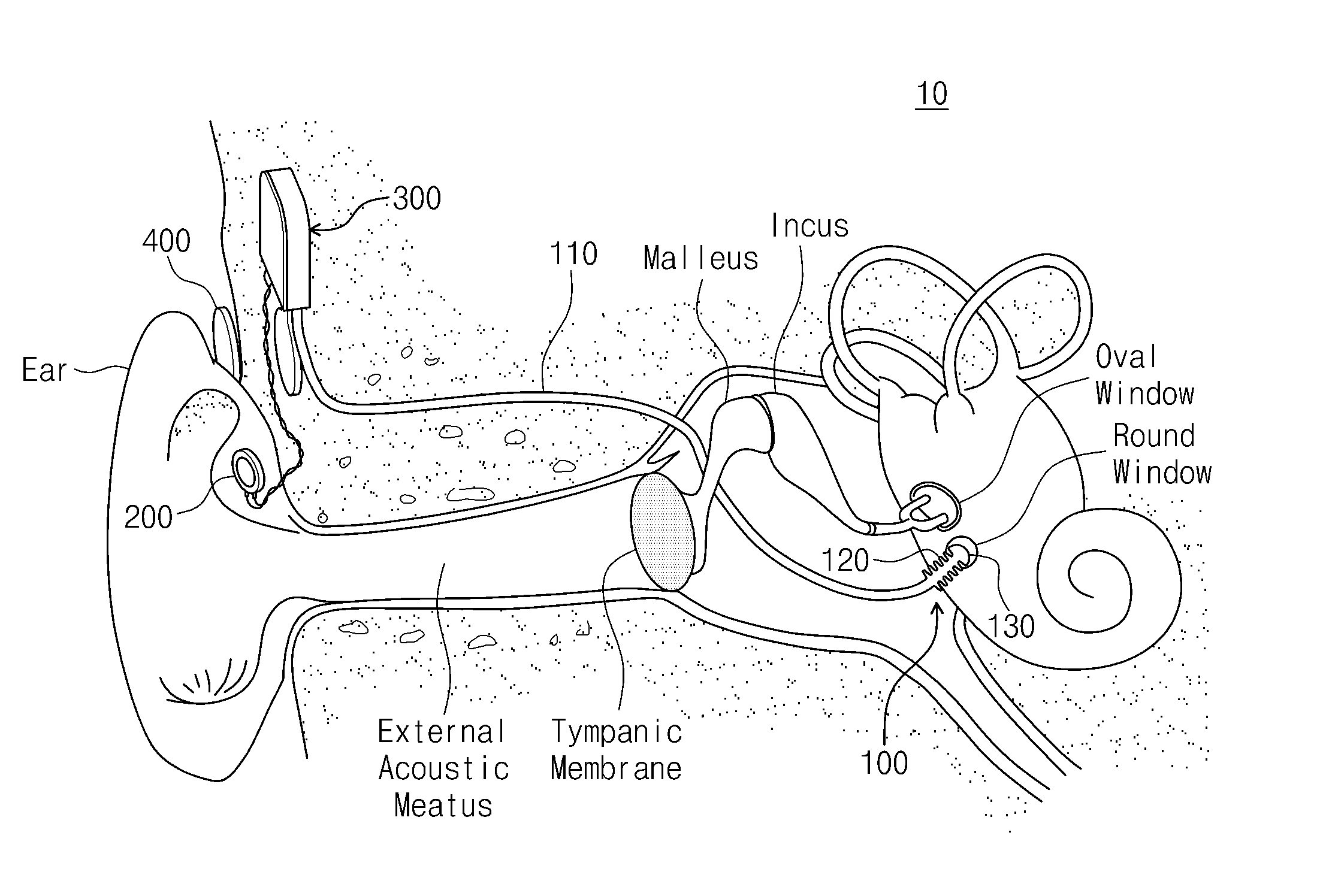
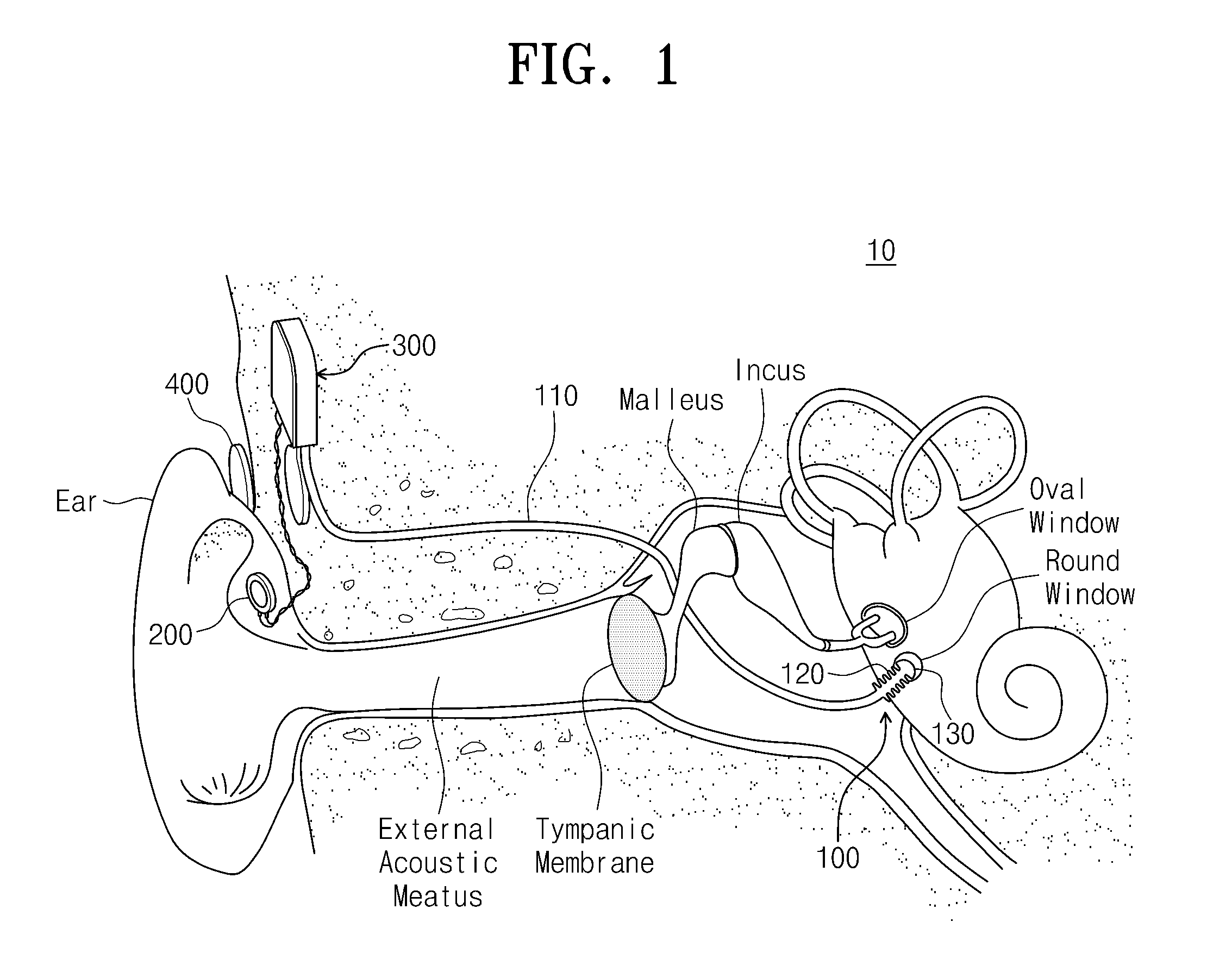
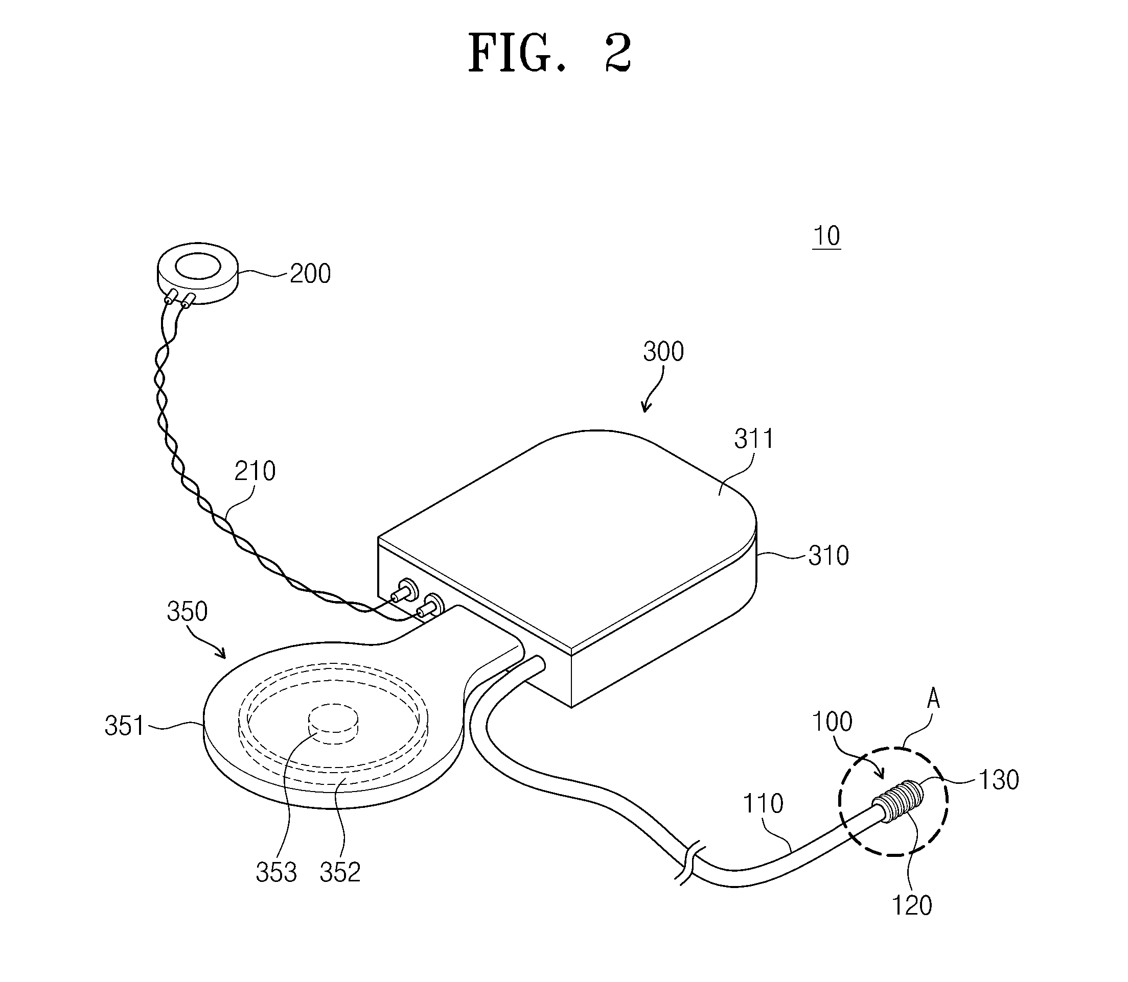
[0055]A vibration transducer according to an embodiment of the present invention may ensure an excellent vibration displacement characteristic by a bellows-type wrinkle member (hereinafter, referred to as a bellows member) formed on an end the...


PUM


Abstract

Provided are a vibration transducer and an implantable hearing aid device. In one embodiment, the implantable hearing aid device includes a signal processing part implantable in a subject, the signal processing part processing a signal from a microphone to output a sound signal, a sound transmission tube configured for transmitting the sound signal to a round window of the subject, and a bellows member disposed at an end side of the sound transmission tube to transmit vibration due to the sound signal to the round window. In other embodiment, the implantable hearing aid device includes a signal processing part implantable in a subject, the signal processing part processing a signal from a microphone to output an electrical signal, a vibration generation part configured for receiving the electrical signal to generate vibration, and a bellows member disposed at an end side of the vibration generation part to transmit the vibration to a round window of the subject. In some embodiments, the vibration generation part includes a magnet member or a piezoelectric vibration member to vibrate in accordance with the electrical signal.

Description

CROSS-REFERENCE TO RELATED APPLICATIONS[0001]This U.S. non-provisional patent application claims priority under 35 U.S.C. §119 of Korean Patent Application No. 10-2014-0029755, filed on Mar. 13, 2014, the entire contents of which are hereby incorporated by reference.BACKGROUND OF THE INVENTION[0002]The present invention disclosed herein relates to a vibration transducer and an implantable hearing aid device.[0003]Recently, hearing loss population in the whole world is continuously increasing due to industrialization and wide prevalence of sound systems having excellent performance. The hearing loss population may be largely classified into three major groups. The first one is a mild and moderate hearing loss group in which the hearing loss is solved with the aid of existing hearing aid devices. The second one is a moderately severe and severe hearing loss group in which the hearing loss is not easily solved with the aid of the existing hearing aid device. The third one is a profound...

Claims


Application Information

Patent Timeline
Patent Type & Authority Applications(United States)
IPC IPC(8): H04R25/00
CPCH04R2225/67H04R25/606H04R9/025
Inventor CHO, JIN-HOSEONG, KI WOONGLEE, JYUNG HYUNLIM, HYUNG GYUSHIN, DONG HO
Owner KYUNGPOOK NAT UNIV IND ACADEMIC COOP FOUND
Why Eureka
Try Eureka