Endoscopic instrument for the connection to an operation robot

a technology of endoscopic instruments and robots, applied in the field of endoscopic instruments for the connection to an operation robot, can solve the problems of increasing the assembly effort on the manufacture of instruments, affecting the size of the instrument housing, and causing the effect of reducing the assembly effor

Inactive Publication Date: 2015-09-24
RICHARD WOLF GMBH
View PDF5 Cites 81 Cited by
  • Summary
  • Abstract
  • Description
  • Claims
  • Application Information

AI Technical Summary

Benefits of technology

[0007]Against this background, it is an object of the invention to provide an endoscopic instrument of the type described above, which has a constructionally simplified movement coupling of the control means for the control of at least one instrument part arranged distally of the shank, and / or of the shank, to a drive unit, and which permits the creation of a compact instrument housing.
[0011]In combination with the pull means which are preferably used for the control of the instrument part arranged at the distal side of the shank, this means that a translation of the coupling element which is produced by the linear drive unit can be transmitted directly onto the pull means given a suitable design. Accordingly, the actuation rollers which until now are to be arranged in the instrument housing are no longer necessary, which leads to a considerable gain in space in the instrument housing, which is to say the creation of a comparatively small instrument housing, wherein the number of the individual components which were necessary until now for the movement transmission of the drive motor onto the control means can be significantly reduced.
[0013]The coupling element is preferably arranged on a track-guided pull slide (carriage) in the instrument housing. A linear guide, in which the pull slide is displaceably guided, is accordingly preferably provided in the instrument housing. E.g. hollow profile rails or two guide strips which are aligned parallel to one another can serve as track guidance for the pull slides in a manner which is simple with regard to the design. The track guide is usefully aligned in the movement direction of the pull means. The pull slide which is led in the track guide is directly connected to the control means, in a particularly space-saving manner.
[0018]The coupling element is advantageously resiliently mounted on the slide in the connection direction of the instrument housing and the linear drive unit, in order to permit the engagement of the projection into the recess of the coupling device after a reference travel of the drive slide. This design permits the evasion of the projection when the projection arranged on the instrument housing side, and the recess formed on the coupling device arranged on the linear drive side are not arranged in a congruent manner on connection of the linear drive unit to the instrument housing, wherein the projection after a reference travel of the drive slide locks into the recess in a manner impinged by spring force. A further measure which is advantageous in this respect lies in the fact that the regions adjacent the recess forming guide ramps for the coupling element, on the drive slides, so that the reference travel of the drive slide is not inhibited by the projection.
[0022]A section of the pull cable is preferably formed by a pull rod. In this context, one envisages both ends of the pull cable being fastened at both ends of the pull rod. The pull cable is preferably fastened on the pull slide on the section formed by the pull rod, wherein the connection of the pull cable to the pull slide is favorably not designed in a rigid manner. Instead, the pull rod is advantageously resiliently mounted on the pull slide on two projections which are distanced to one another in the pull direction of the pull cable, in order to protect the pull cable from an overload.

Problems solved by technology

Moreover, various cable deflections which are necessary in the instrument housing moreover also have an additional disadvantageous influence on the dimensions of the instrument housing and increase the assembly effort on manufacture of the instrument.
This size of the instrument housing has been shown to be disadvantageous if several of these shank instruments are to be applied together in a restricted space, as is the case with single-port operations for example, with which the shank instruments are simultaneously led to the region of operation via a common body opening.

Method used


Image

  • Endoscopic instrument for the connection to an operation robot
  • Endoscopic instrument for the connection to an operation robot
  • Endoscopic instrument for the connection to an operation robot

Examples


Embodiment Construction

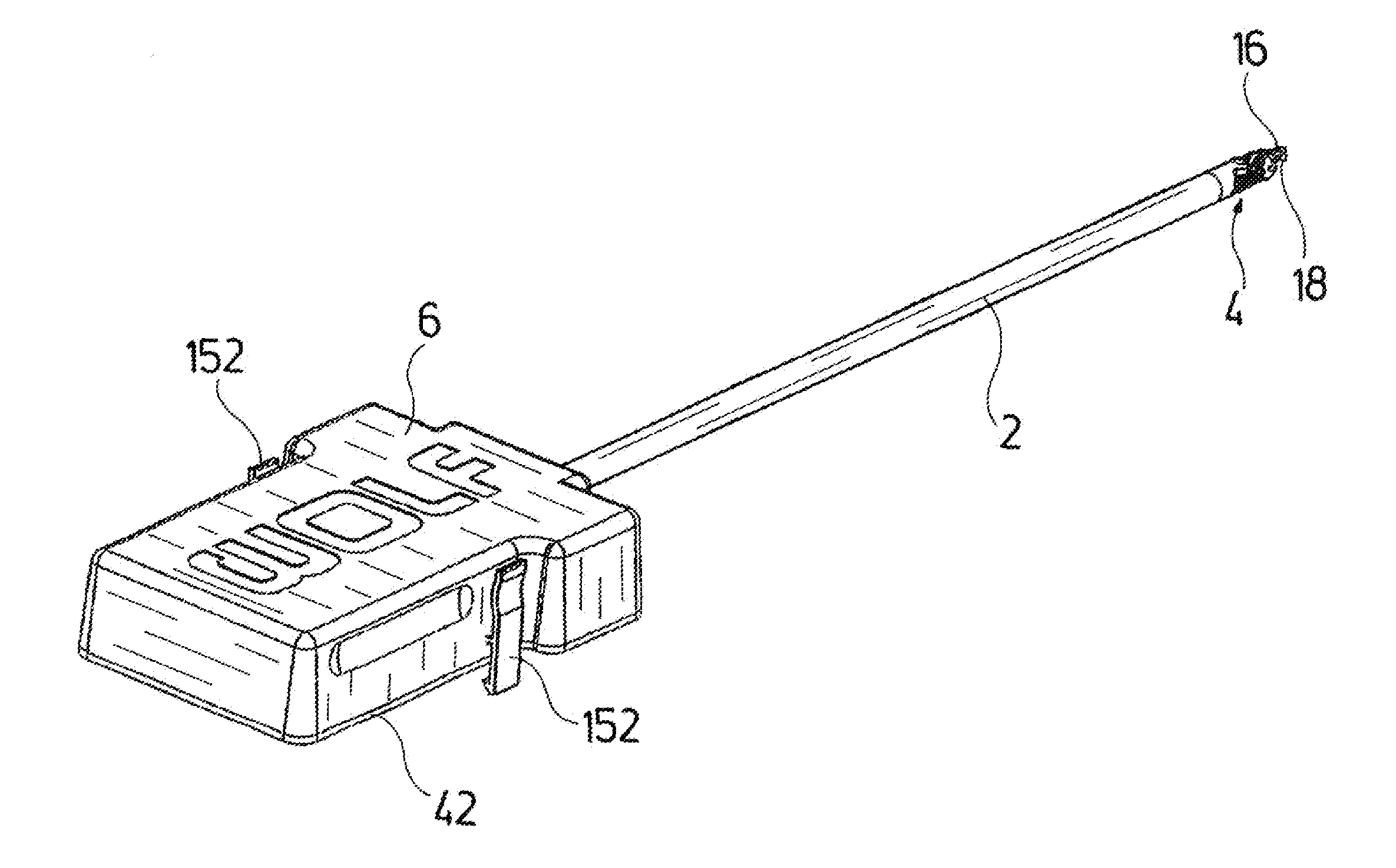
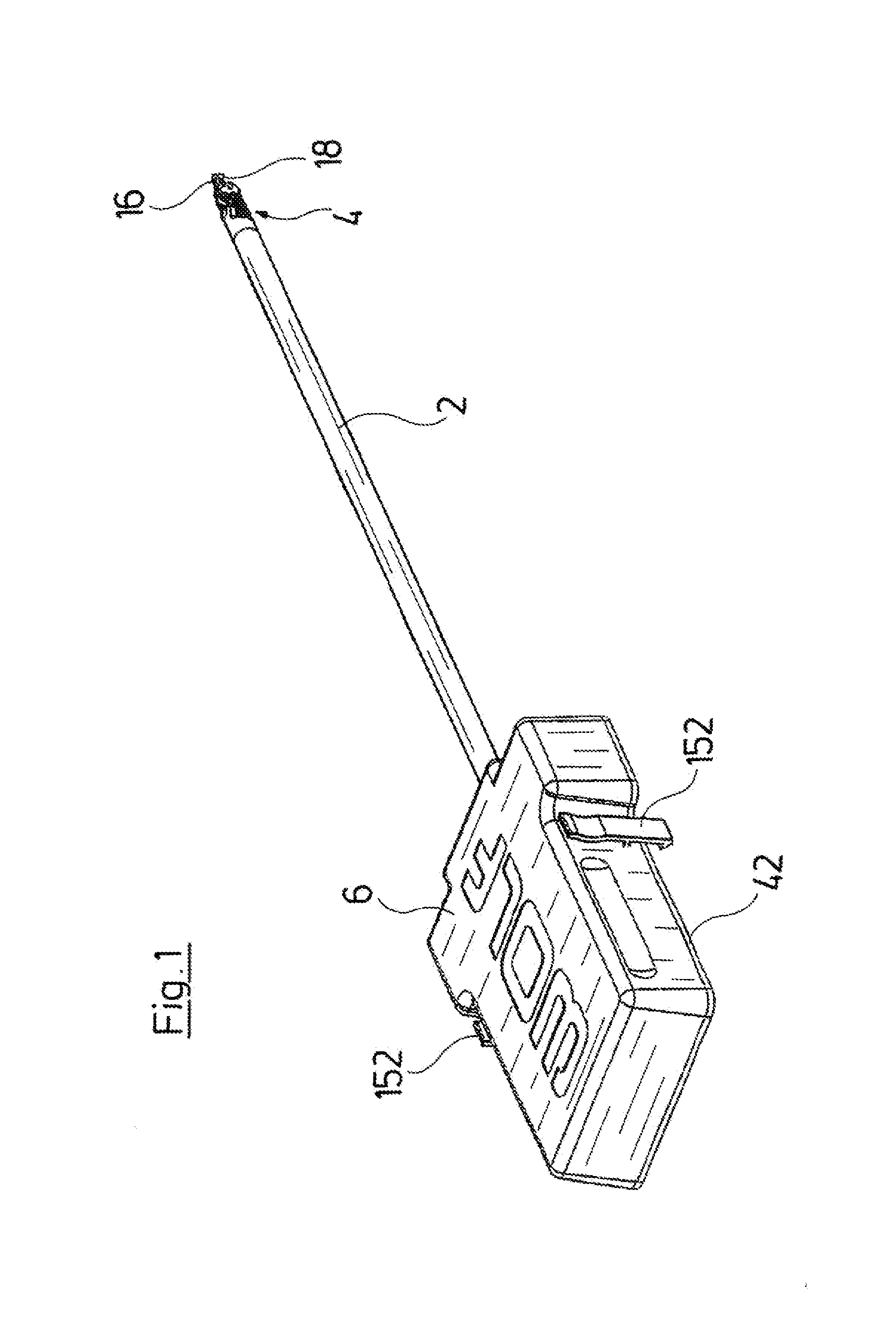
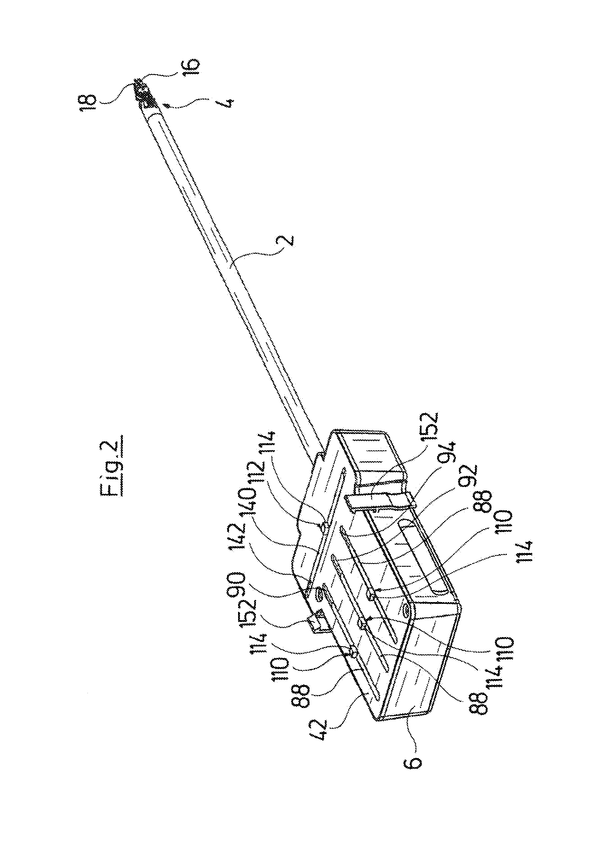
[0044]With regard to the endoscopic instrument represented in the drawing, it is the case of a shank instrument with a shank 2 which is designed as a hollow shank and on which an instrument head 4 is arranged at the distal side. An instrument housing 6, into which a proximal end region of the shank 2 engages and there in a mounting device 8 (FIGS. 4 and 5) is rotatably mounted relative to the instrument housing 6, is provided at the proximal side of the shank 2.

[0045]It is evident from FIGS. 5, 14 and 15 that the instrument head 6 is pivotably articulated on the shank 2 via a joint pin 10 and is pivotable in a plane transverse to the longitudinal extension of the shank 2. A tool carrier 12 is articulated on the instrument head 4 at the distal side via a joint pin 14, in a manner such that the tool carrier 12 can pivot in a plane normal to the pivot plane of the instrument head 4. The tool carrier 12 carries a jaw tool with two jaw parts 16 and 18 which are pivotable relative to one ...


PUM


Abstract

An endoscopic instrument for the connection to an operation robot. The endoscopic instrument includes an instrument housing, to which a shank with at least one instrument part arranged at the distal side of the shank connects distally. The instrument part and / or the shank are movable relative to the instrument housing and for this are each actively connected to control. The control can be coupled, via a translatorily movable coupling element coupled thereto and projecting out of the instrument housing, to a linear drive unit which can be connected to the instrument housing at the outer side.

Description

CROSS REFERENCE TO RELATED APPLICATIONS[0001]This application claims the benefit of priority under 35 U.S.C. §119 of German Patent Application DE 10 2014 205 036.7 filed Mar. 18, 2014, the entire contents of which are incorporated herein by reference.FIELD OF THE INVENTION[0002]The invention relates to an endoscopic instrument for the connection to an operation robot, with an instrument housing, with a shank which connects to the instrument housing, and with at least one instrument part arranged on a distal side of the shank, wherein the instrument part and / or the shank are movable relative to the instrument housing and for this are each actively connected to a control means (a control).BACKGROUND OF THE INVENTION[0003]Operation robots are nowadays applied with an increasing number of surgical operations. Such an operation robot is known for example from US 2009 / 0234371 A1. This operation robot comprises several robot arms, at whose distal ends an endoscopic shank instrument is arra...

Claims


Application Information

Patent Timeline
Patent Type & Authority Applications(United States)
IPC IPC(8): A61B19/00A61B17/00
CPCA61B19/2203A61B17/00234A61B2019/2215A61B2017/00477A61B2017/00473A61B2019/2242A61B2019/2234A61B2017/00327A61B34/71A61B34/30
Inventor PRESTEL, STEPHANMUNNIG, SORENTEICHTMANN, ELMARWEHRHEIM, FRANK
Owner RICHARD WOLF GMBH
Why Eureka
Try Eureka