Front structure of motorcycle

a front structure and motorcycle technology, applied in the direction of bicycle equipment, roof, steering device, etc., can solve the problems of limited space utilization efficiency, large size of the slide mechanism, limited slide stroke of the screen, etc., to reduce the size of the screen mechanism, and reduce the effect of the screen mechanism

Active Publication Date: 2015-09-24
HONDA MOTOR CO LTD
View PDF11 Cites 10 Cited by
  • Summary
  • Abstract
  • Description
  • Claims
  • Application Information

AI Technical Summary

Benefits of technology

[0028]Meanwhile, the present invention does not use an air cylinder but uses the left and right rails, and thus the screen mechanism can be reduced in size. Additionally, since the duct is arranged between the paired left and right rails, limited space can be utilized efficiently. Reduction in the size of the screen mechanism and effective utilization of space allows more freedom in designing the front portion of the vehicle, whereby appearance of the vehicle can be improved more easily.
[0029]In another embodiment, the duct includes the curved portion that comes closer to the visor as it approaches the air intake. Since the duct comes close to the visor around the air intake, the gap between the duct and the visor can be reduced. Reduction in the gap allows a larger amount of traveling wind to be taken into the duct from the air intake. It is possible to suppress variation in the amount of traveling wind flowing through between the screen and the visor, as well as between the upper end of the duct and the screen, even when the screen is vertically slid to a different position. Accordingly, the amount of traveling wind flowing to the rear of the screen does not vary largely, so that traveling wind can be constantly guided to the rear of the screen. As a result, ease in steering can be enhanced even more while maintaining a predetermined windbreak performance.
[0030]In another embodiment, the lower edge of the screen is formed so as to follow the shape of the mirror covers. Since the lower edge of the screen is formed so as to follow the shape of the mirror covers, the lower edge of the screen can be brought closer to the mirror covers when the screen is moved downward. Additionally, the movable range in which the screen slides can be made larger than a case where the lower edge of the screen is formed so as not to follow the shape of the mirror cover. As a result, the windbreak performance of the screen can be enhanced.
[0031]In another embodiment, in side view, the rail is curved in such a manner as to protrude downward, and the screen is curved in such a manner as to protrude upward. By thus assigning predetermined curvatures to the rail and the screen, an upper end of the visor and the screen forming a gap can be constantly kept as close as possible, even when the screen is slid. A part of traveling wind having entered from the air intake flows through between the visor and the screen without entering the duct. At this time, since the gap between the upper end of the visor and the screen is small, and variation in the gap caused by sliding of the screen is kept small, the flow amount of traveling wind can be suppressed. Accordingly, the amount of traveling wind flowing to the rear of the screen does not vary largely, so that traveling wind can be constantly guided to the rear of the screen. As a result, ease in steering can be enhanced even more while maintaining a predetermined windbreak performance.

Problems solved by technology

Conventionally, in a screen slide mechanism using an air cylinder, for example, the size of the slide mechanism tended to become large, and the slide stroke of the screen was limited.
Additionally, since the duct is arranged between the paired left and right rails, limited space can be utilized efficiently.

Method used


Image

  • Front structure of motorcycle
  • Front structure of motorcycle
  • Front structure of motorcycle

Examples


Embodiment Construction

[0060]Hereinafter, an embodiment of the present invention will be described in detail. In the drawings and the example, directions such as “upper,”“lower,”“front,”“rear,”“left,” and “right” are those seen from a rider of a motorcycle.

[0061]Examples of the present invention will be described with reference to the drawings.

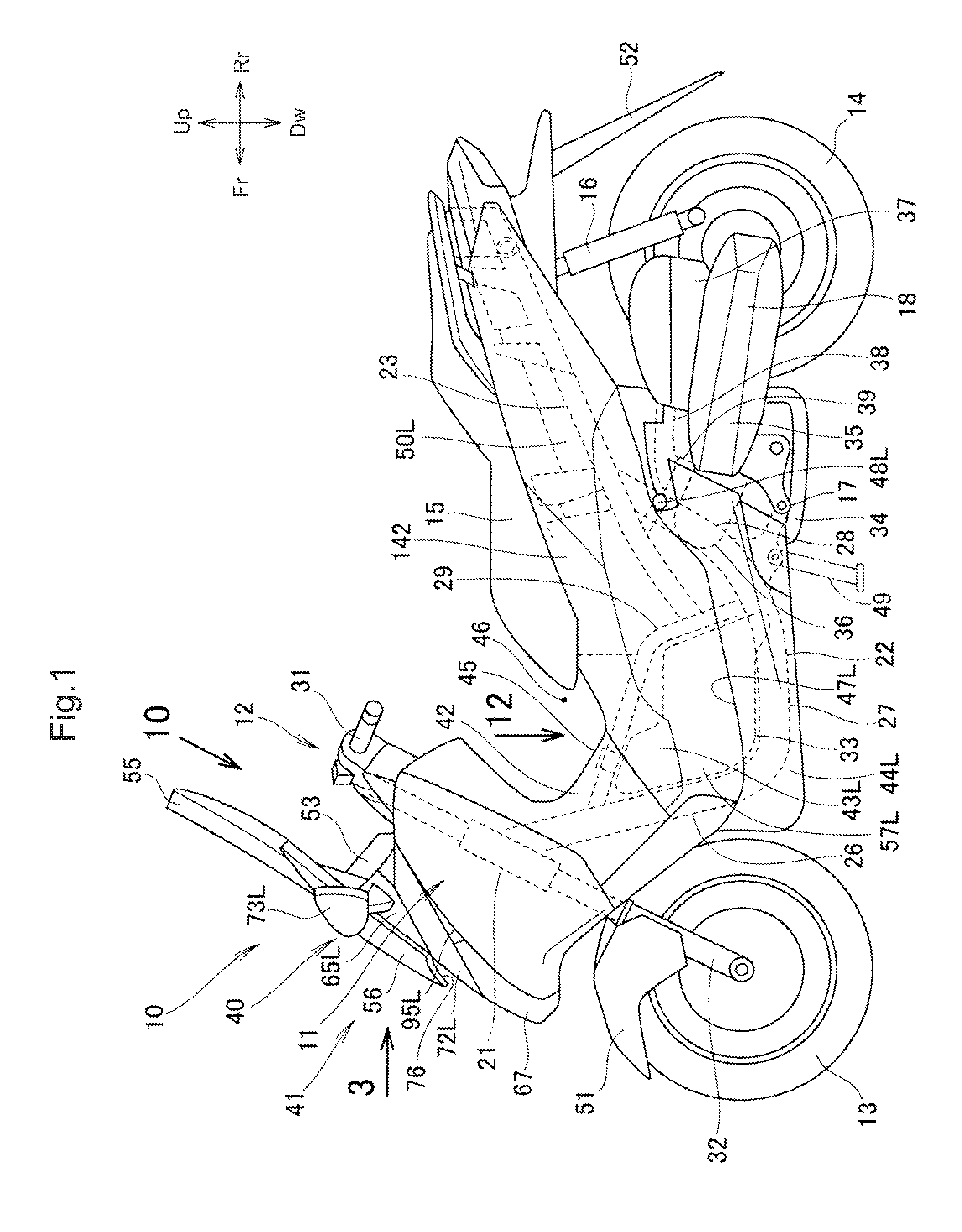
[0062]As shown in FIG. 1, a motorcycle 10 is a straddle type vehicle that includes a body frame 11, a front wheel steering portion 12 steerably supported by a front portion of the body frame 11 and including a front wheel 13, and a seat 15 supported by the body frame 11 and on which a rider sits. A pivot shaft 17 is provided in the body frame 11 in a position below the seat 15, and a power unit 18 extends toward the vehicle rear from the pivot shaft 17, and serves as a power source as well as a swing arm. A rear wheel 14 is attached to a rear end portion of the power unit 18, and a cushion unit 16 is bridged across the rear end of the power unit 18 and the body fram...


PUM


Abstract

In a motorcycle including a screen, a meter panel is arranged at the vehicle front of a rider, and a visor is arranged at the vehicle front of the meter panel. The visor is higher than the meter panel to form an air intake for taking in traveling wind between the visor and the meter panel. A duct extends to a rear side of the screen from the air intake at the vehicle rear of the visor, so that the duct can introduce traveling wind to the rear side of the screen.

Description

BACKGROUND[0001]1. Field[0002]The present invention relates to improvement in a front structure of a motorcycle including a screen.[0003]2. Description of the Related Art[0004]There is known a front structure of a motorcycle including a screen for shielding traveling wind (see FIGS. 3, 4, 5 of Japanese Utility Model Registration Application Publication No. Hei 4-37089, hereinafter Patent Document 1.[0005]As shown in FIGS. 3 and 5 of Patent Document 1, an upper cowl “11” (the quoted number indicates a reference numeral used in Patent Document 1. The same shall apply hereinafter.) is provided in a front portion of the vehicle, an air intake opening “15” is formed in the upper cowl “11,” and an outer screen “20” is fixed to an attachment portion “19” of the upper cowl “11” above the opening “15.” An inner screen “21” is supported in a vertically slidable manner to the outer screen “20” at the vehicle rear of the outer screen “20.” The outer screen “20” and the inner screen “21” constit...

Claims


Application Information

Patent Timeline
Patent Type & Authority Applications(United States)
IPC IPC(8): B62J17/04B62K21/12B62J23/00B62K11/02
CPCB62J17/04B62K11/02B62J2099/004B62J23/00B62K21/12B62J17/02B62J17/06B62J35/00B62K19/46B62K2202/00B62J17/10B62J45/00
Inventor HORIUCHI, TETSUYAMAMOTO, KANTASUDA, TOMOKATSUSATO, KAZUOKURAMITSU, TOMOFUMIMIURA, TOSHIO
Owner HONDA MOTOR CO LTD
Why Eureka
Try Eureka