
Full field strain sensors using mechanoluminescence materials

Inactive Publication Date: 2015-09-24
THE UNIVERSITY OF AKRON
View PDF8 Cites 22 Cited by
  • Summary
  • Abstract
  • Description
  • Claims
  • Application Information

AI Technical Summary

Benefits of technology

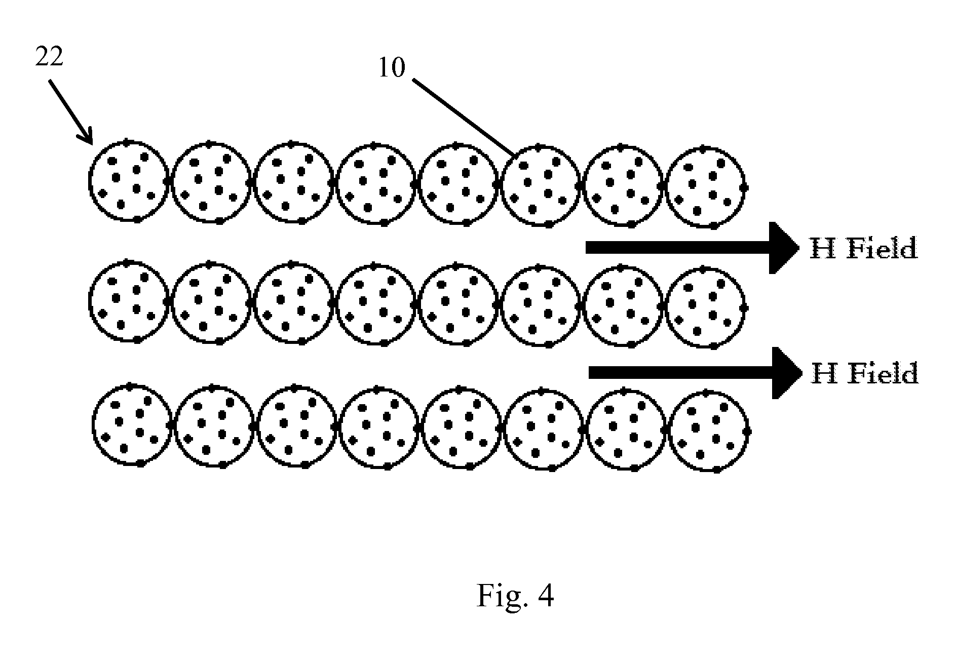
The present invention provides a method for using a mechanoluminescence assembly to observe stress distributions on a stressed substrate. The method involves coating the mechanoluminescence material with a coating and dispersing it in a medium that carries the coated material. The medium is applied to the substrate and forms a solid film. The solid film is then subjected to a magnetic field to align the mechanoluminescence assembly. The method can be used to determine whether the substrate has undergone strain by analyzing the color change of the solid film. The invention also provides a sensor for visualizing stress and a method for coating the mechanoluminescence material.

Problems solved by technology

One such attempt includes the use of mechanophores and utilizing the opening and closing of the covalent bonds caused by mechanical straining However, this requires a large strain in order to induce color changes.
However, photonic materials are limited by the poor quality of coloration and the particular wavelength bands that can be used.
Additionally, currently developed mechanoluminescence materials do not provide any information about the particular direction at which the mechanical strain is applied.

Method used


Image

  • Full field strain sensors using mechanoluminescence materials
  • Full field strain sensors using mechanoluminescence materials
  • Full field strain sensors using mechanoluminescence materials

Examples


Embodiment Construction

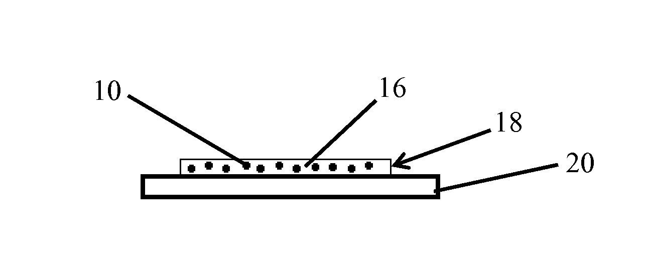
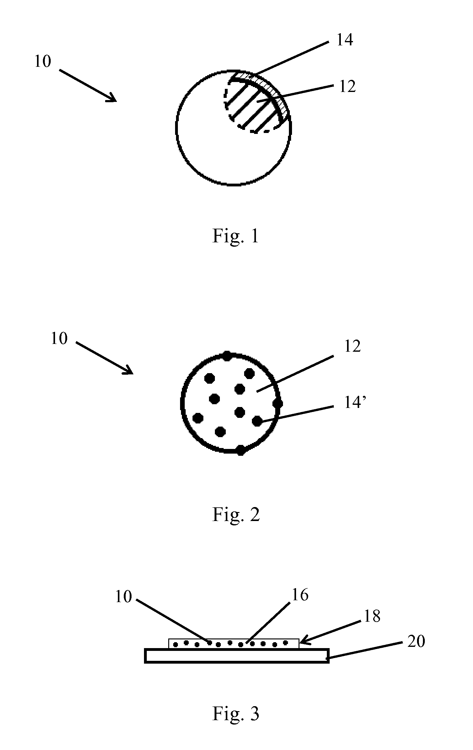
[0032]A mechanoluminescence (ML) material assembly, generally indicated by the numeral 10, includes a mechanoluminescence material 12 and a coating 14, 14′ that at least partially coats ML material 12. A plurality of the assemblies 10 can be dispersed in a medium 16, to form a mechanoluminescence-material-containing medium, generally indicated by the numeral 18, which can be applied to a substrate 20. Assembly 10 has mechanoluminescence properties based on mechanoluminescence material 12. Further, coating 14, 14′ gives one or more additional properties to assembly 10 based on the particular coating 14, 14′ that is utilized.

[0033]ML material 12 can be said to form the core of assembly 10. In one or more embodiments, ML material 12 is a mechanoluminescence particle. In one or more embodiments, ML material 12 is a mechanoluminescent ceramic particle. Mechanoluminescence can be defined as light emission resulting from any mechanical action on a solid.

[0034]In one or more embodiments, ML...


PUM

PropertyMeasurementUnit
Temperatureaaaaaaaaaa
Coloraaaaaaaaaa
Magnetic fieldaaaaaaaaaa

Abstract

A sensor for visualizing stress includes a medium and a plurality of mechanoluminescence assemblies dispersed therein. A mechanoluminescence assembly can include a mechanoluminescence material and a coating material, where the mechanoluminescence material is at least partially coated with the coating material. A method of using the sensor can include applying the medium to a substrate and allowing the medium to form a solid film on the substrate. Methods of using the mechanoluminescence assemblies are also provided.

Description

CROSS-REFERENCE TO RELATED APPLICATION[0001]This application claims priority to U.S. Provisional Patent Application No. 61 / 968,100 filed on Mar. 20, 2014, and U.S. Provisional Patent Application No. 61 / 968,089 filed on Mar. 20, 2014, the contents of which are incorporated herein by reference.FIELD OF THE INVENTION[0002]The present invention generally relates to improved mechanoluminescence materials and associated methods of production and use. The present invention further relates to mechanoluminescence materials having a coating where the coating gives one or more additional properties to the coated assembly. The present invention further relates to mechanoluminescence materials that are coated with titanium dioxide and dispersed in a medium containing a dye. The present invention further relates to mechanoluminescence materials that are coated with magnetic nanoparticles.BACKGROUND OF THE INVENTION[0003]It is previously known to use mechanoluminescence materials for the visualiza...

Claims


Application Information

Patent Timeline
IPC IPC(8): C09K11/02G01L1/24G01N21/88H01F1/01
CPCC09K11/025G01N21/8803G01L1/24H01F1/01H01F1/0054F21K2/04G01L1/247
Inventor ZHU, JIAHUAYUN, GUNJIN
Owner THE UNIVERSITY OF AKRON
Learn More