Film forming apparatus

a technology of film forming and film, which is applied in the direction of chemical vapor deposition coating, coating, metal material coating process, etc., can solve the problems of long replacement period, complicated structure of shower head, and technical features of gas supply units, and achieve high in-plane uniformity and effective replacement

Active Publication Date: 2015-09-24
TOKYO ELECTRON LTD
View PDF13 Cites 316 Cited by
  • Summary
  • Abstract
  • Description
  • Claims
  • Application Information

AI Technical Summary

Benefits of technology

[0013]In view of the above, the present invention provides a film forming apparatus capable of forming a film having high in-plane uniformity and ensuring effective replacement between reactant gases and a replacement gas.

Problems solved by technology

This makes the structure of the shower head complicated.
Even if reactant gases and a replacement gas are selectively supplied to one side of the gas diffusion space, a long period of time is required for the replacement operation.
However, in the shower head for selectively supplying the reactant gases and the replacement gas, there is no description on technical features of the gas supply units which are required to improve uniformity of a film to be formed.

Method used


Image

  • Film forming apparatus
  • Film forming apparatus
  • Film forming apparatus

Examples


reference example 1-1

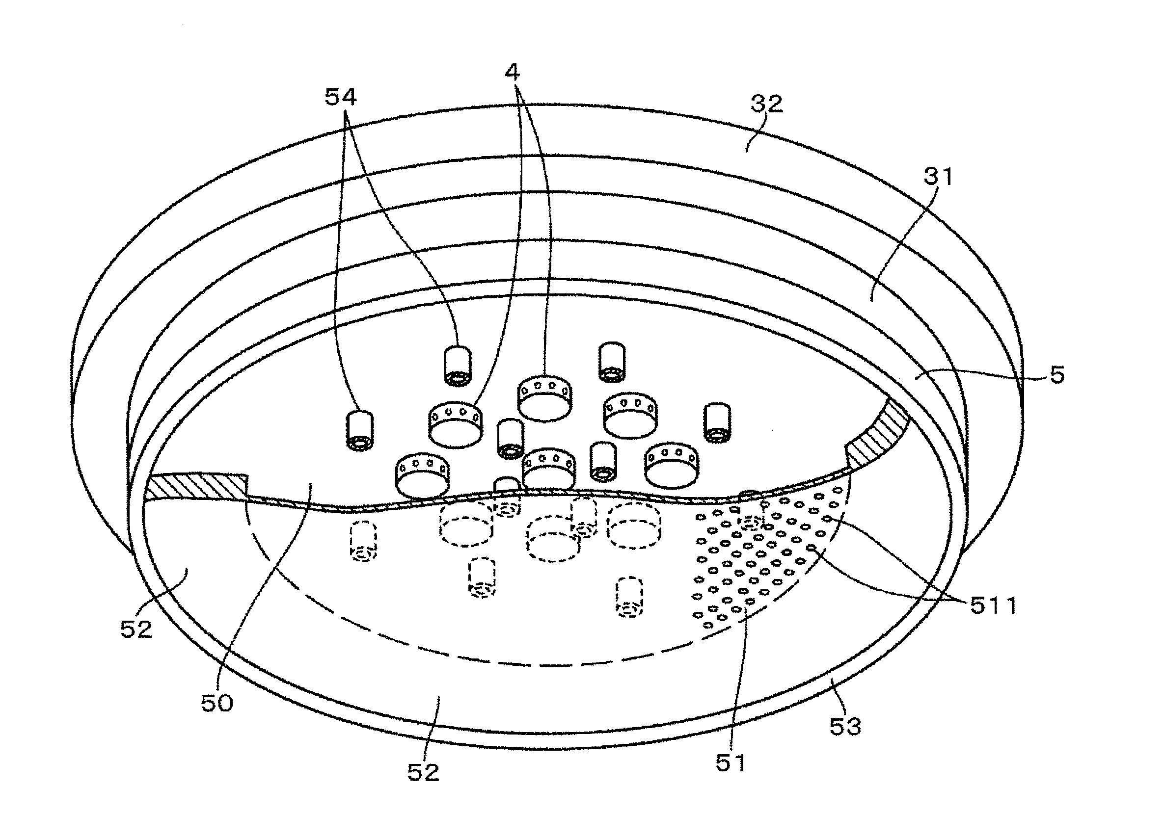
[0096]A TiN film was formed under the same conditions of the test example 1-1 by using the film forming apparatus shown in FIG. 9. Hereinafter, the film forming apparatus shown in FIG. 9 will be described. A shower head 5a having a diameter of 200 mm is provided at a central portion of a ceiling plate 31a having an inclined surface 310 that becomes gradually wider from a central side toward the peripheral side. Further, eight gas supply units 4a, each having gas discharge openings 42, are arranged inside the shower head 5a as in the example shown in FIG. 6. A central gas supply unit 4a has a diameter of 15 mm and the gas supply units 4a arranged in a circular ring shape have a diameter of 10 mm. A circular ring shape formed by arranging eight gas supply units 4a has a diameter of 100 mm. The gas is supplied into the processing space 313 through the gas supply openings 521 formed at the side surface as well as at the bottom surface of the shower head 5a. In FIG. 9, like reference num...

reference example 4-1

[0116]The gas diffusion state in the shower head 5a of the shower head 5a shown in FIG. 9 was simulated. The diameter of the gas supply units 4a surrounding the gas supply unit 4a provided at the central portion was set to about 8 mm.

[0117]FIG. 15A shows the simulation result of the test example 4-1. FIG. 15B shows the simulation result of the reference example 4-1. Dotted arrows in the drawings indicate portions of the shower heads 5 and 5a (gas diffusion space 50) where gases discharged from the gas supply units 4 and 4a reach.

[0118]According to the simulation results shown in FIGS. 15A and 15B, the gas supply unit 4 having a larger diameter can uniformly distribute the gas in the shower head 5. According to another simulation of gas flow near the gas supply units 4 and 4a, in the case of the gas supply unit 4 having a large diameter, a horizontal vector of the gas supplied from the gas supply unit 4 is relatively greater and the gas can be uniformly supplied to a wider area in th...


PUM

PropertyMeasurementUnit
diameteraaaaaaaaaa
diameteraaaaaaaaaa
temperatureaaaaaaaaaa

Abstract

A film forming apparatus for performing a film forming process by sequentially supplying a plurality of reactant gases to a substrate and supplying a replacement gas includes a mounting table configured to mount thereon a substrate, and a shower head having a flat surface facing the mounting table and a plurality of gas supply opening. An annular protrusion is provided at the shower head to form a gap between the annular protrusion and a top surface of the mounting table. A plurality of gas supply units is provided at a ceiling portion at an upper side of the shower head. Each gas supply unit has gas discharge openings formed along a circumferential direction. The diffusion space is disposed such that an outer periphery of the diffusion space is located at an inner side of an outer periphery of the substrate mounted on the mounting table in a plan view.

Description

CROSS-REFERENCE TO RELATED APPLICATIONS[0001]This application claims priority to Japanese Patent Application No. 2014-055146 filed on Mar. 18, 2014, the entire contents of which are incorporated herein by reference.FIELD OF THE INVENTION[0002]The present invention relates to a film forming apparatus for forming a film by sequentially supplying a plurality of reactant gases that react with one another to a substrate.BACKGROUND OF THE INVENTION[0003]As for a method for forming a film on a substrate, e.g., a semiconductor wafer (hereinafter, referred to as “wafer”), there are known a so-called ALD (Atomic Layer Deposition) method for sequentially supplying a plurality of reactant gases that react with one another to a wafer, and a MLD (Multi Layer Deposition) method (hereinafter, both will be referred to as “ALD method”).[0004]There are suggested various gas supply units for supplying reactant gases to a wafer in such a film forming method. For example, Japanese Patent Application Publ...

Claims


Application Information

Patent Timeline
Patent Type & Authority Applications(United States)
IPC IPC(8): C23C16/455C23C16/46C23C16/52C23C16/44C23C16/458
CPCC23C16/45565C23C16/4412C23C16/46C23C16/52C23C16/458C23C16/34C23C16/45544C23C16/45574
Inventor SAITOU, TETSUYAOOTA, TOMOHIROTAKAGI, TOSHIO
Owner TOKYO ELECTRON LTD
Why Eureka
Try Eureka