
Apparatus and method for inspecting a surface of a sample

a surface inspection and apparatus technology, applied in material analysis using wave/particle radiation, instruments, nuclear engineering, etc., can solve the problems of less suitable inspection of small samples and large distance between individual spots on the specimen surface, and achieve the effect of enhancing detection arrangement and reducing blur

Active Publication Date: 2015-09-24
TECH UNIV DELFT
View PDF12 Cites 14 Cited by
  • Summary
  • Abstract
  • Description
  • Claims
  • Application Information

AI Technical Summary

Benefits of technology

This patent describes an apparatus for inspecting small samples using a single objective lens and a detector. By arranging the charged particle beams and detecting them on the sample surface, the apparatus can inspect smaller samples compared to previous methods. The use of a detector that allows for efficient detection of the charged particles makes this possible. The apparatus also includes a second lens system that can be controlled to reduce blur and improve resolution. Additionally, the apparatus includes a beam limiting aperture to control the contrast and size of the detected particles. Overall, this patent describes a more efficient and accurate method for inspecting small samples.

Problems solved by technology

A disadvantage of this system is that the distance between the individual spots on the specimen surface is relatively large due to the use of one objective microlens per electron beam.
Consequently the known system is less suitable for inspecting small samples.

Method used


Image

  • Apparatus and method for inspecting a surface of a sample
  • Apparatus and method for inspecting a surface of a sample
  • Apparatus and method for inspecting a surface of a sample

Examples


Embodiment Construction

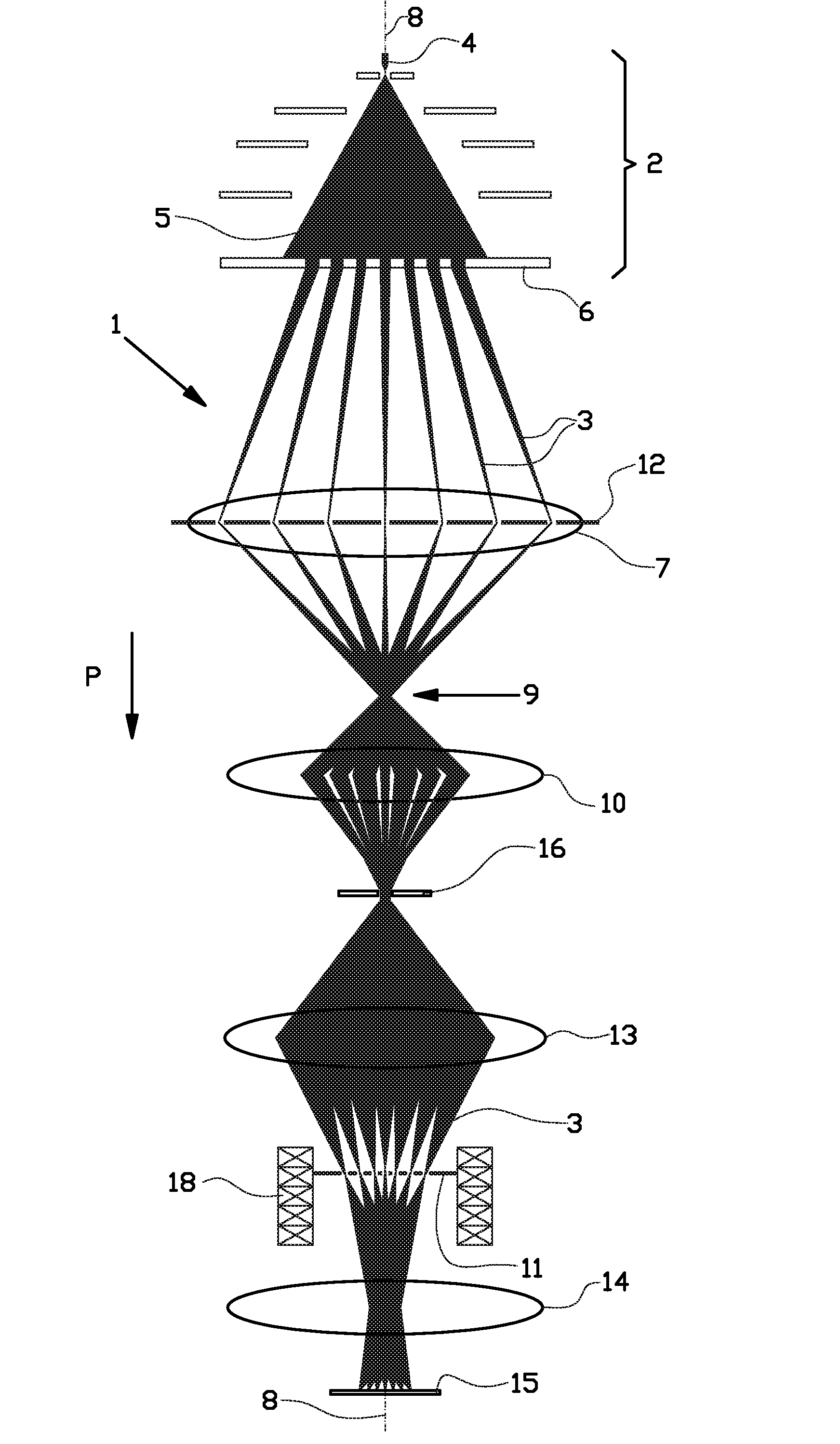
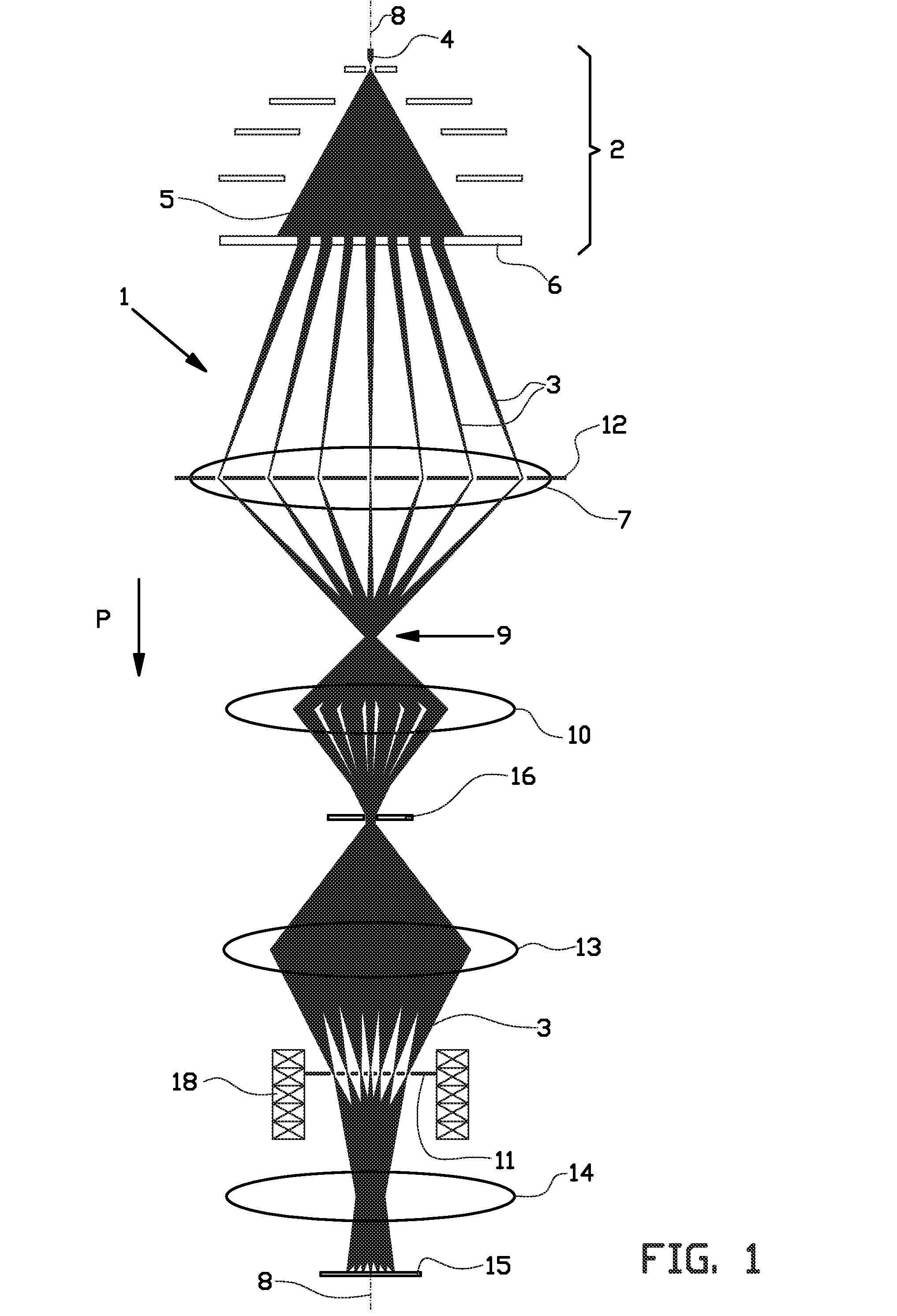
[0053]FIG. 1 shows an example of a Multi-Beam Scanning Electron Microscope (MBSEM) of the invention.

[0054]The MBSEM 1 comprises a multi beam charged particle generator 2 for generating an array of primary charged particle beams 3, in this case an array of primary electron beams 3. The multi beam electron generator 2 comprises at least one electron source 4 for generating a diverging electron beam 5. The diverging electron beam 5 is split into an array of focused primary electron beams 3 by an aperture lens array 6. The primary electron beams 3 are subsequently directed towards a sample 15, as schematically indicated by the arrow P.

[0055]The multiple images of the source 4 are positioned on the object principle plane of an accelerator lens 7. The accelerator lens 7 directs the primary electron beams 3 towards the optical axis 8 and creates a first common cross-over 9 of all the primary electron beams 3.

[0056]The first common cross-over 9 is imaged by the magnetic condenser lens 10 on...


PUM

PropertyMeasurementUnit
angleaaaaaaaaaa
angleaaaaaaaaaa
angleaaaaaaaaaa

Abstract

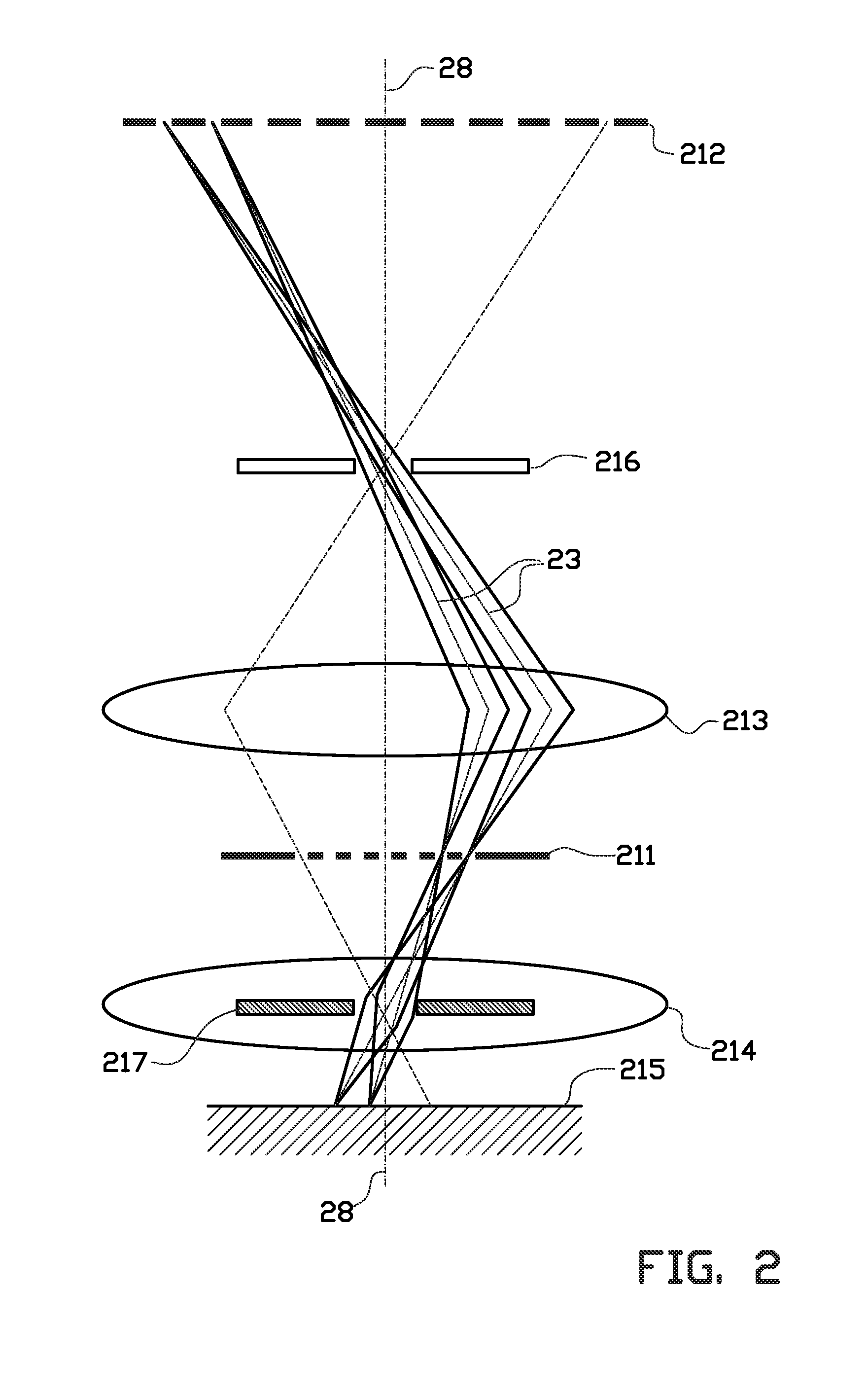
The invention relates to an apparatus and method for inspecting a sample. The apparatus comprises a generator for generating an array of primary charged particle beams (33), and a charged particle optical system with an optical axis (38). The optical system comprises a first lens system (37, 310) for focusing all primary beams (33) into a first array of spots in an intermediate plane, and a second lens system (313, 314) for focusing all primary beams (33) into a second array of spots on the sample surface (315). The apparatus comprises a position sensitive backscattered charged particle detector (311) positioned at or near the intermediate plane. The second lens system comprises an electromagnetic or electrostatic lens which is common for all charged particle beams. Preferably the second lens system comprises a magnetic lens for rotating the array of primary beams (33) around the optical axis (38) to position the second array of charged particle spots with respect to the first array at an angle.

Description

BACKGROUND[0001]The invention relates to an apparatus and a method for inspecting a surface of a sample. In particular the invention relates to an apparatus for inspecting a sample surface using a plurality of charged particle beams, such as a multi-beam scanning electron microscope. The invention may be applied to charged particles of any type, such as electrons, positrons, ions and others.[0002]The invention relates to an apparatus for detecting backscattered charged particles, such as electrons. These backscattered charged particles have almost the same energy as the primary charged particles. It is usually assumed that the charged particles lose up to a few hundred electron volts in the sample before coming out again. The angular distribution of the backscattered charged particles is much larger than the angular distribution of the primary charged particle beams. The backscattered charged particles that travel close to the axis of corresponding primary charged particle beam will...

Claims


Application Information

Patent Timeline
Patent Type & Authority Applications(United States)
IPC IPC(8): H01J37/28H01J37/244G01N23/225
CPCH01J37/28G01N23/2251G01N2223/33G01N2223/418G01N2223/413H01J37/244G01N2223/3307H01J37/3177H01J2237/2446
Inventor KRUIT, PIETER
Owner TECH UNIV DELFT
Learn More