Fuel cell vehicle

a fuel cell and vehicle technology, applied in the direction of cell components, cell component details, electrochemical generators, etc., can solve the problem that the leakage of hydrogen cannot be reliably ventilated to the outside of the vehicle, and achieve the effect of easy and reliable discharge to the outsid

Inactive Publication Date: 2015-09-24
HONDA MOTOR CO LTD
View PDF15 Cites 37 Cited by
  • Summary
  • Abstract
  • Description
  • Claims
  • Application Information

AI Technical Summary

Benefits of technology

[0013]Further, even if the vehicle is tilted in any direction, i.e., tilted toward the front or back side, or tilted toward the left or right side, the fuel gas can be discharged to the outside from at least one of the openings. Thus, with the simple structure, the fuel gas leaked into the stack case can be discharged to the outside easily and reliably.

Problems solved by technology

Therefore, leaked hydrogen cannot be ventilated to the outside of the vehicle reliably.

Method used


Image

  • Fuel cell vehicle
  • Fuel cell vehicle
  • Fuel cell vehicle

Examples


Embodiment Construction

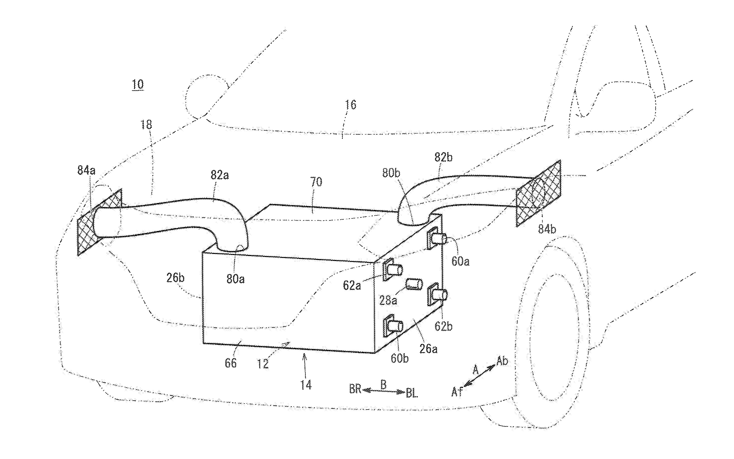
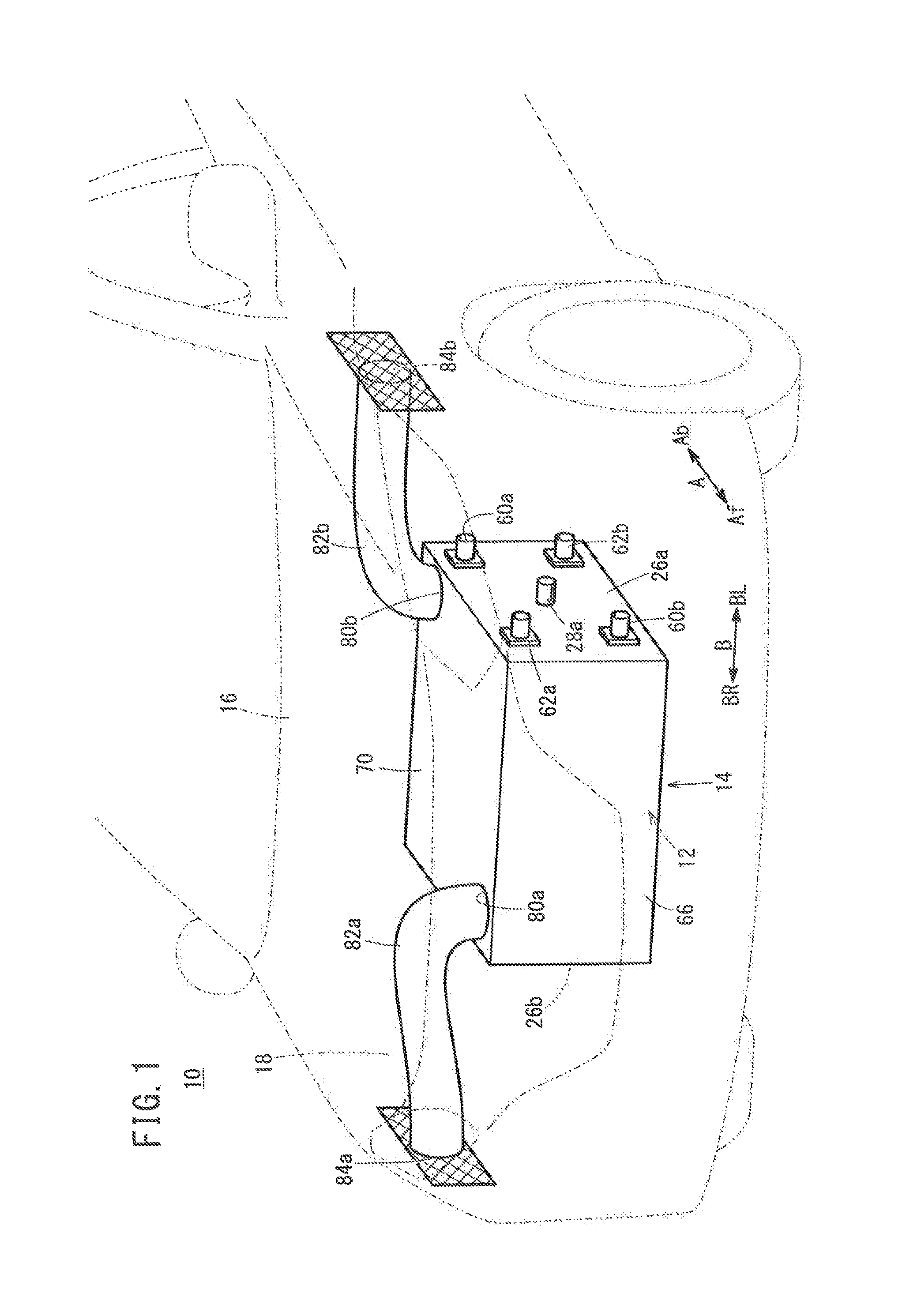
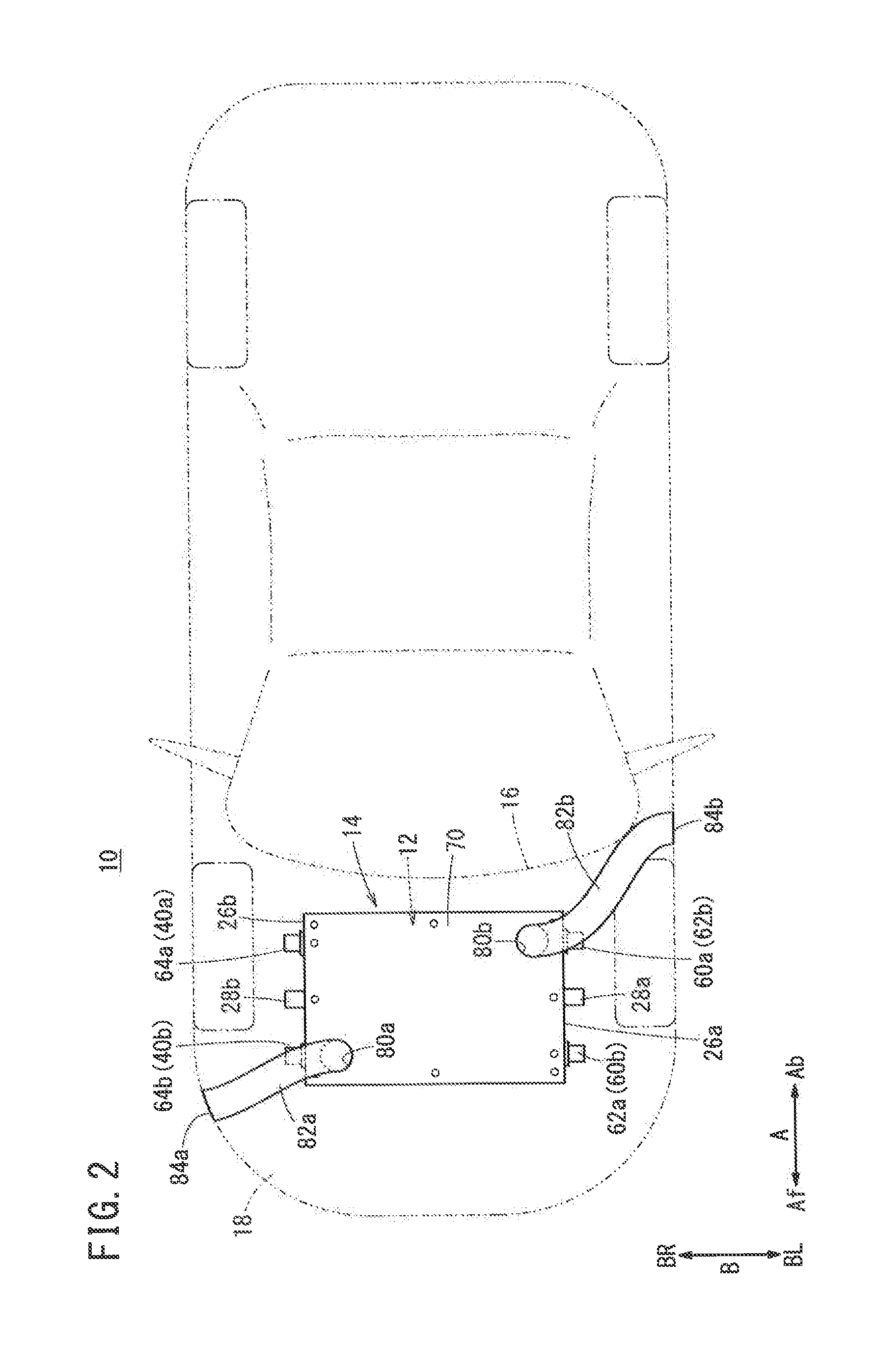
[0027]A fuel cell vehicle 10 according to a first embodiment of the present invention shown in FIGS. 1 to 3 is a fuel cell electric vehicle, for example. In the fuel cell vehicle 10, a stack case 14 containing a fuel cell stack 12 is provided in a front room (motor room) 18 provided in front of a dashboard 16.

[0028]As shown in FIG. 4, the fuel cell stack 12 is formed by stacking a plurality of fuel cells 20 in a vehicle width direction indicated by an arrow B. At one end of the fuel cells 20 in the stacking direction, a first terminal plate 22a is provided. A first insulating plate 24a is provided outside the first terminal plate 22a, and a first end plate 26a is provided outside the first insulating plate 24a. At the other end of the fuel cells 20 in the stacking direction, a second terminal plate 22b is provided. A second insulating plate 24b is provided outside the second terminal plate 22b, and a second end plate 26b is provided outside the second insulating plate 24b. The first...


PUM

PropertyMeasurementUnit
widthaaaaaaaaaa
cross sectional areasaaaaaaaaaa
areaaaaaaaaaaa

Abstract

A stack case of a fuel cell vehicle contains a fuel cell stack, and the stack case is mounted in a front room. Openings are formed at one pair of diagonal positions of an upper panel forming an upper surface of the stack case. The inner space of the stack case is connected to the outside through the openings. Exhaust gas ducts connected to the openings are opened to the outside of the front room.

Description

CROSS-REFERENCE TO RELATED APPLICATIONS[0001]This application is based upon and claims the benefit of priority from Japanese Patent Applications No. 2014-057384 filed on Mar. 20, 2014 and No. 2015-025256 filed on Feb. 12, 2015, the contents all of which are incorporated herein by reference.BACKGROUND OF THE INVENTION[0002]1. Field of the Invention[0003]The present invention relates to a fuel cell vehicle equipped with a fuel cell stack formed by stacking a plurality of fuel cells. The fuel cell stack is placed in a stack case, and the stack case is mounted in a front room formed in front of a dashboard.[0004]2. Description of the Related Art[0005]For example, a solid polymer electrolyte fuel cell employs a polymer ion exchange membrane as an electrolyte membrane, and the polymer electrolyte membrane is interposed between an anode and a cathode to form a membrane electrode assembly (MEA). The membrane electrode assembly and a pair of separators sandwiching the membrane electrode asse...

Claims


Application Information

Patent Timeline
Patent Type & Authority Applications(United States)
IPC IPC(8): H01M8/04H01M8/10H01M8/24
CPCH01M8/04201H01M8/24H01M2008/1095H01M2250/20H01M8/1018H01M8/2475H01M8/04089H01M8/2484Y02T90/40Y02E60/50H01M8/2483H01M8/0267H01M8/2457
Inventor NAITO, HIDEHARUNISHIYAMA, TAKAYUKIMATSUMOTO, MITSUNORI
Owner HONDA MOTOR CO LTD
Why Eureka
Try Eureka