LED (light-emitting diode) string derived controller power supply

a technology of light-emitting diodes and controllers, applied in the direction of electric lighting sources, electroluminescent light sources, semiconductor lamp usage, etc., can solve the problems of wasting energy and adding some complexity to the circuit, and achieve the effect of improving efficiency and reducing complexity

Active Publication Date: 2015-09-24
SIGNIFY HLDG BV
View PDF1 Cites 29 Cited by
  • Summary
  • Abstract
  • Description
  • Claims
  • Application Information

AI Technical Summary

Benefits of technology

[0007]A control circuit for controlling power supplied to one or more lighting devices, an integrated circuit (“IC”) for controlling such ...

Problems solved by technology

Generating the controller power supply voltage from the typical li...

Method used


Image

  • LED (light-emitting diode) string derived controller power supply
  • LED (light-emitting diode) string derived controller power supply
  • LED (light-emitting diode) string derived controller power supply

Examples


Embodiment Construction

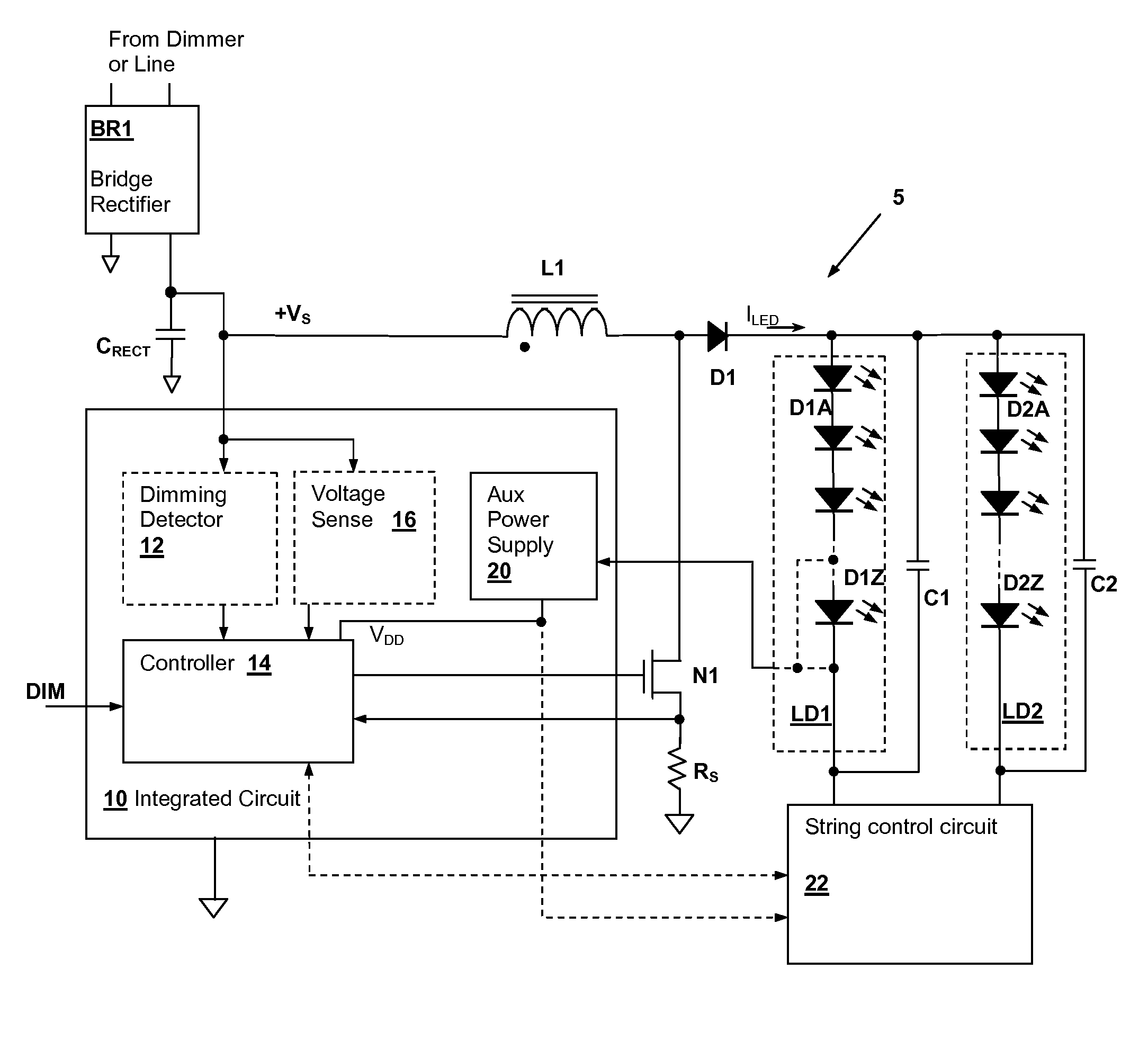
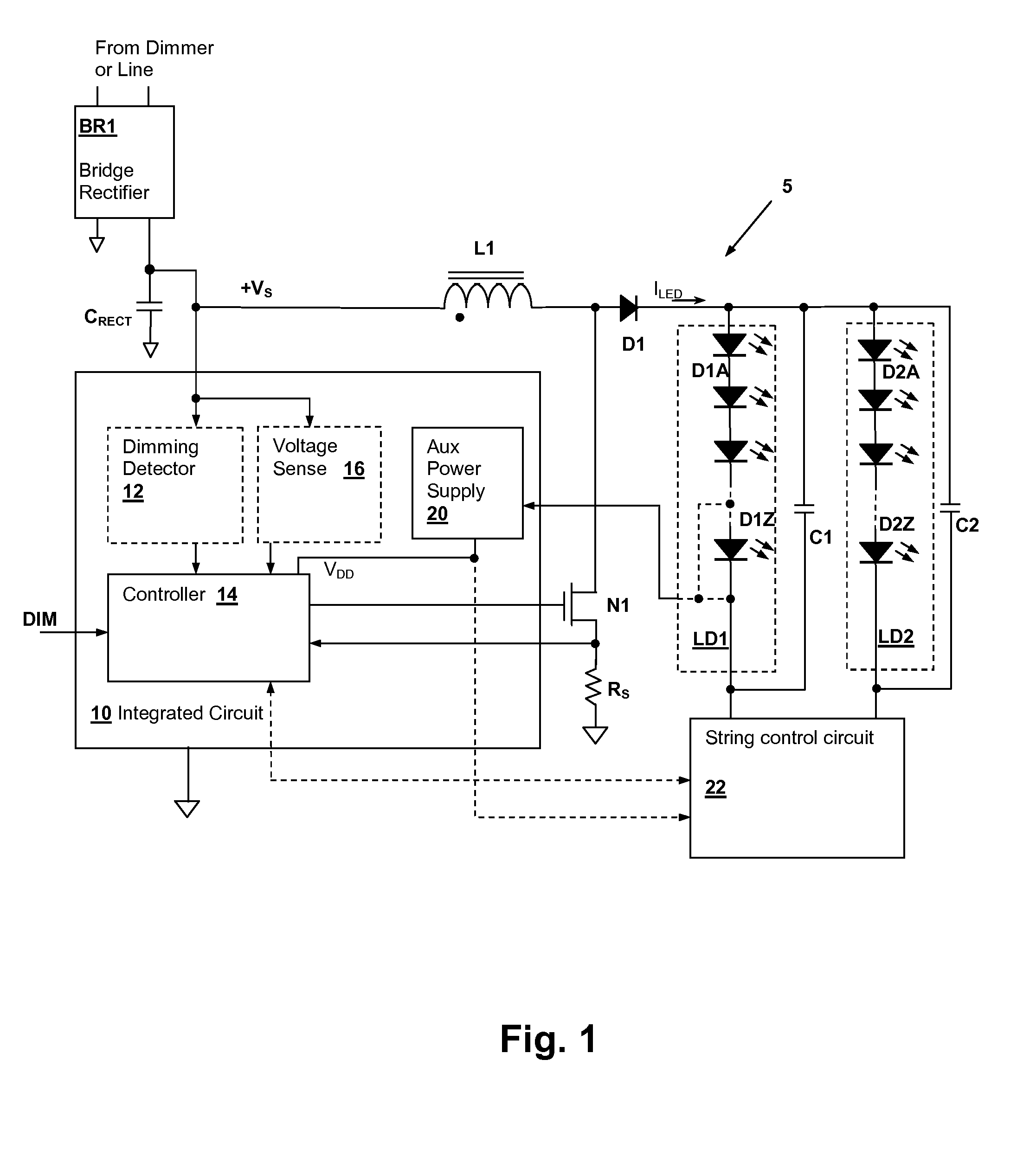
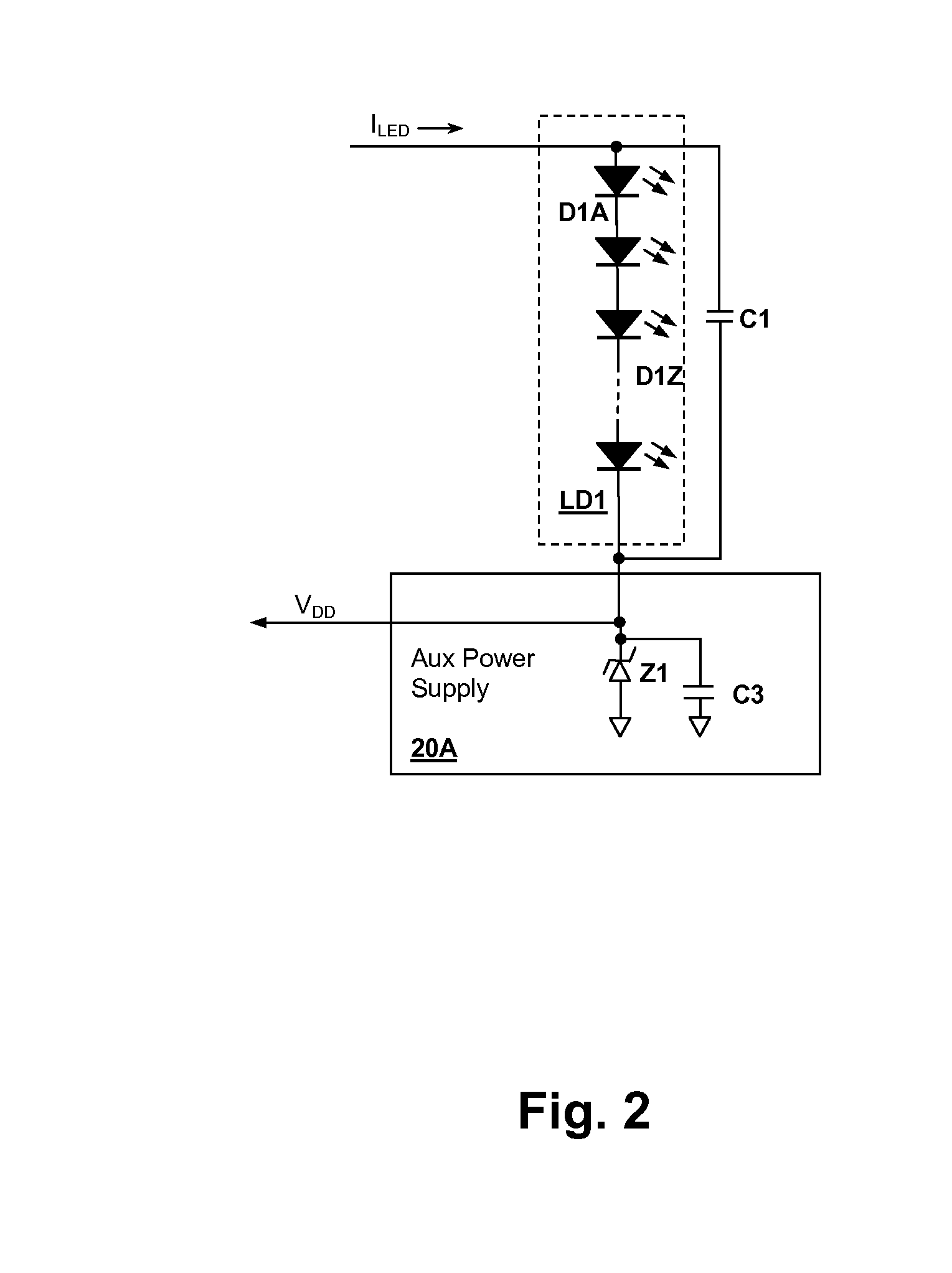
[0016]The present disclosure reveals circuits and methods for powering and controlling strings of series-connected light-emitting diodes (LEDs), in which auxiliary power for control circuits that control a switching power supply within a lighting device including the LEDs is provided from an LED string itself. In particular embodiments, strings of light-emitting diodes (LEDs) are packaged to replace incandescent lamps. A power supply voltage is supplied or generated from a terminal of an LED string within the lighting device, which may be a terminal within the LED string, or an end of the LED string. Since the voltage provided from the terminal is substantially greater than a voltage provided from the rectified AC line voltage at the input of the switching power supply, energy that would otherwise be wasted in producing the auxiliary power supply voltage is conserved.

[0017]Referring now to FIG. 1, an exemplary lighting circuit 5 is shown. An inductor L1 provides a magnetic storage e...


PUM


Abstract

An LED lighting device includes an auxiliary power supply that supplies power to a control circuit of the LED lighting device that receives an input from a terminal of a light-emitting diode (LED) string of the lighting device that has a substantially lower voltage than the line voltage to which the lighting device is connected. The terminal may be within the LED string, or may be an end of the string. A linear regulator may be operated from the voltage drop across a number of the LEDs in the string so that the energy wasted by the auxiliary power supply is minimized. In other designs, the auxiliary power supply may be intermittently connected in series with the LED string only when needed. The intermittent connection can be used to forward bias a portion of the LED string when the voltage supplied to the LED string is low, increasing overall brightness.

Description

BACKGROUND OF THE INVENTION[0001]1. Field of the Invention[0002]The present invention relates generally to lighting device power sources such as those included within light-emitting diode (LED) lamps, and in particular to a control circuit for an LED lighting device power source that is powered from a LED string controlled by the control circuit.[0003]2. Background of the Invention[0004]Lighting control and power supply integrated circuits (ICs) are in common use in both electronic systems and in replaceable consumer lighting devices, e.g., light-emitting-diode (LED) and compact fluorescent lamp (CFL) replacements for traditional incandescent light bulbs.[0005]In order to power LED lighting device from a typical AC power line voltage, the AC power line voltage must somehow be reduced to the relatively low voltage required by the LEDs in the lighting device. One manner in which the reduction is accomplished is to connect the LEDs in series to form a string, which is then supplied fro...

Claims


Application Information

Patent Timeline
IPC IPC(8): H05B33/08H05B44/00
CPCH05B33/0815H05B33/0845H05B39/047H05B41/2827H05B41/28H05B45/44H05B45/38H05B45/3725H05B45/10H05B45/48H05B45/46Y02B20/30
Inventor MELANSON, JOHN L.KING, ERICSINGH, RAHUL
Owner SIGNIFY HLDG BV
Why Eureka
Try Eureka