Medical apparatus for determining a maximum energy map

a technology of determining the maximum energy map and medical equipment, which is applied in the field of high intensity focused ultrasound, can solve the problems of easier control of tissue heating with ultrasound than cavitation, and achieve the effect of facilitating the calculation of the thermal property map

Inactive Publication Date: 2015-10-01
KONINKLJIJKE PHILIPS NV
View PDF2 Cites 3 Cited by
  • Summary
  • Abstract
  • Description
  • Claims
  • Application Information

AI Technical Summary

Benefits of technology

[0024]Typically the maximum energy for a particular location may be limited by previous sonications because ultrasound passes through the subject on the way to the focal point of the high-intensity focused ultrasound system. In particular the near field region is a region between a transducer for the high-intensity focused ultrasound system and the focal point. By performing repeated sonications the near field region can become heated. It may be necessary to allow the sonication points to be sonicated at a later time to prevent from overheating the near field region. Execution of the instructions further causes the processor to receive a selection of the at least one sonication volume from a user interface. A sonication volume as used herein is a volume of the subject which is determined to be or selected to be sonicated. Essentially the operator of the medical apparatus can look at the maximum energy map and see which regions of the subject the operator can deposit energy into at the current time. By displaying this data spatially the operator may be able to more efficiently use the medical apparatus. Displaying the maximum energy map may identify regions which the operator can sonicate immediately or after a short period of time. This may reduce the downtime and the costs associated with high-intensity focused ultrasound systems.
[0029]In another embodiment the ultrasound transducer comprises multiple ultrasound transducer elements. The multiple ultrasound transducer elements are controllable. By controllable it is understood herein that the phase and / or amplitude of electrical power supplied to the transducer elements may be controlled individually or as groups. The multiple ultrasound transducer elements are operable for adjusting an ultrasound beam path between the ultrasound transducer and the sonication volume. The predicted ultrasound beam geometry is descriptive of the ultrasound beam path. The thermoacoustic model is further operable for determining the predicted thermal property map by calculating adjustments to the ultrasound beam geometry using a beam path ultrasound transducer model. Essentially the path of the beam may be approximated or predicted using a model. Simple models such as the ray tracing method or assuming a geometric shape which represent the beam path are computationally easy ways of calculating this.
[0041]In another embodiment execution of the instructions causes the processor to display the temperature change rate map on the display. This embodiment may be beneficial because the temperature change rate map may indicate properties of the tissue of the subject useful for deciding on where to sonicate.
[0047]In another embodiment execution of the instructions further causes the processor to generate sonication commands using the selection of at least one sonication volume. Execution of the instructions further cause the processor to control the high-intensity focused ultrasound system to sonicate the at least one sonication volume using the sonication commands.

Problems solved by technology

These vibrations induce tissue heating as they are damped, and they can also lead to cavitation.
However, heating tissue with ultrasound is easier to control than cavitation.

Method used


Image

  • Medical apparatus for determining a maximum energy map
  • Medical apparatus for determining a maximum energy map
  • Medical apparatus for determining a maximum energy map

Examples


Embodiment Construction

[0065]Like numbered elements in these figures are either equivalent elements or perform the same function. Elements which have been discussed previously will not necessarily be discussed in later figures if the function is equivalent.

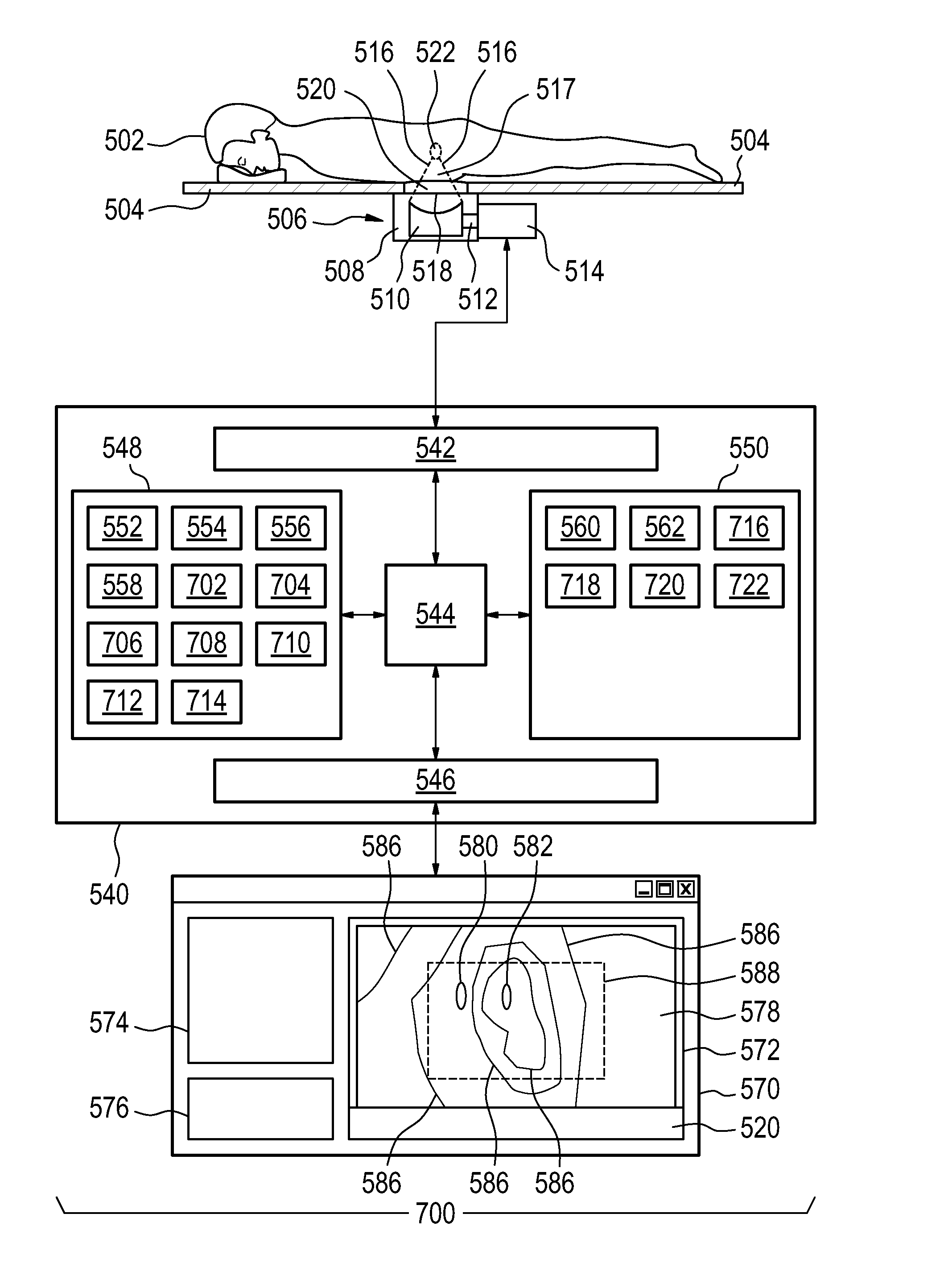
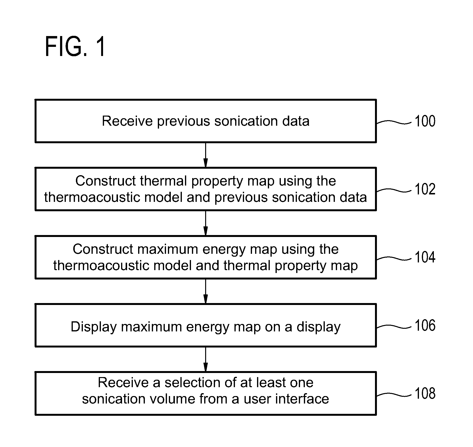
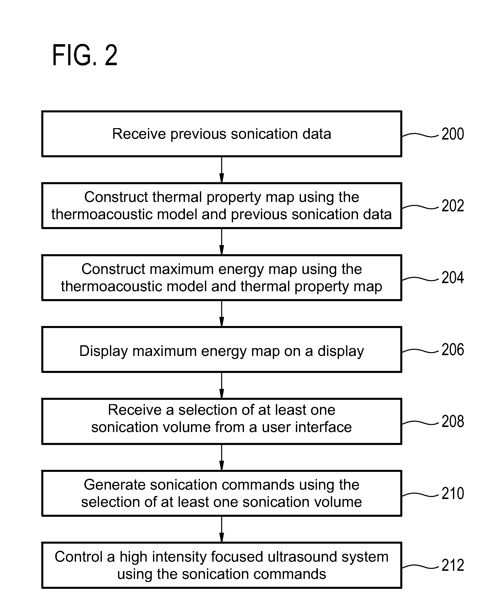
[0066]FIG. 1 shows a block diagram which illustrates a method according to an embodiment of the invention. First in step 100 previous sonication data is received. The previous sonication data is descriptive of a previous sonication of the subject by a high-intensity focused ultrasound system. Next in step 102 a thermal property map is constructed of the subject using the previous sonication data and a thermoacoustic model. The thermal property map is descriptive of a thermal property. The thermal property map is spatially dependent and temporally dependent. Next in step 104 a maximum energy map is determined or constructed using the thermoacoustic model and the thermal property map. The maximum energy is time dependent. Next in step 106 the maximum ener...


PUM


Abstract

The invention provides for a medical apparatus (500, 700, 800) comprising a high intensity focused ultrasound system (506). The medical apparatus further comprises a memory (550) for storing machine executable instructions (560, 562) for execution by a processor (544). Execution of the instructions cause the processor to: receive (100, 200, 304) previous sonication data (522) descriptive of a previous sonication of the subject; construct (102, 202, 306) a thermal property map (554) of the subject using the previous sonication data and a thermoacoustic model (562); determine (104, 204, 308) a maximum energy map (556) using the thermoacoustic model and the thermal property map, wherein the maximum energy is time dependent; display (106, 206, 310) the maximum energy map on a display (672); and receive (108, 208, 312) a selection of at least one thermoacoustic model and thermal property map sonication volume (580, 582) from a user interface (570).

Description

TECHNICAL FIELD[0001]The invention relates to high intensity focused ultrasound, in particular to the determination of a maximum sonication energy.BACKGROUND OF THE INVENTION[0002]Ultrasound from a focused ultrasonic transducer can be used to selectively treat regions within the interior of the body. Ultrasonic waves are transmitted as high energy mechanical vibrations. These vibrations induce tissue heating as they are damped, and they can also lead to cavitation. Both tissue heating and cavitation can be used to destroy tissue in a clinical setting. However, heating tissue with ultrasound is easier to control than cavitation.[0003]Ultrasonic treatments can be used to ablate tissue and to kill regions of cancer cells selectively. This technique has been applied to the treatment of uterine fibroids, and has reduced the need for hysterectomy procedures.[0004]To selectively treat tissue, a focused ultrasonic transducer can be used to focus the ultrasound on a particular treatment or t...

Claims


Application Information

Patent Timeline
Patent Type & Authority Applications(United States)
IPC IPC(8): A61N7/02
CPCA61N7/02A61B2017/00084A61N2007/0091A61N2007/0095A61B2090/374
Inventor NURMILAUKAS, KIRSI ILONAYLIHAUTALA, MIKA PETRIVUORINEN, REKO TAPIOENHOLM, JULIA KRISTINATOLO, JAAKKO JUHANI
Owner KONINKLJIJKE PHILIPS NV
Why Eureka
Try Eureka