
Compression assembly for a turbine engine

a turbine engine and compression assembly technology, applied in the direction of machines/engines, liquid fuel engines, rotors, etc., can solve the problems of limiting the acceleration capacity of the turboshaft engine, affecting the performance of the turbine engine, and affecting the efficiency of the turbine engin

Active Publication Date: 2015-10-01
SAFRAN HELICOPTER ENGINES
View PDF3 Cites 2 Cited by
  • Summary
  • Abstract
  • Description
  • Claims
  • Application Information

AI Technical Summary

Benefits of technology

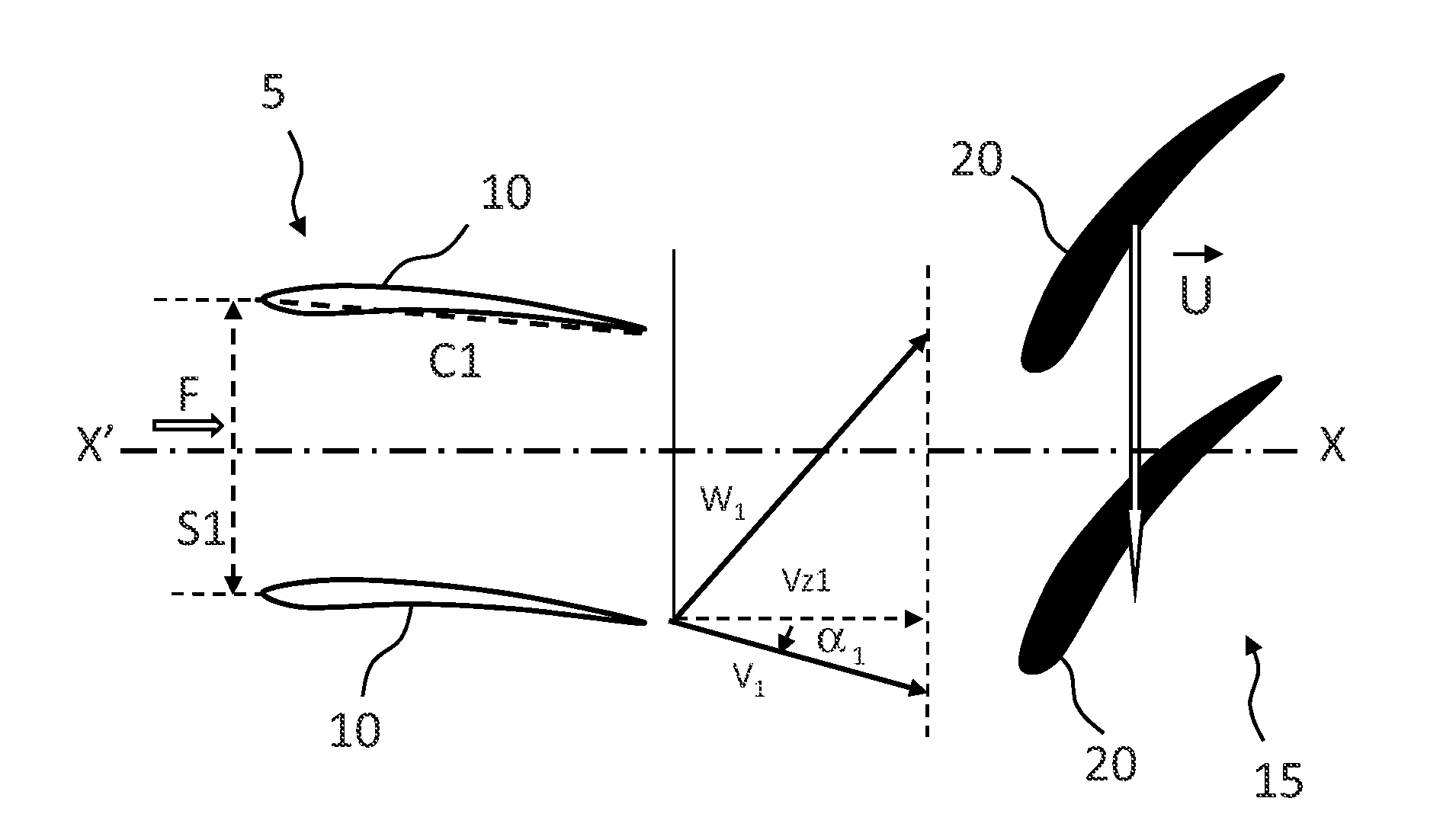
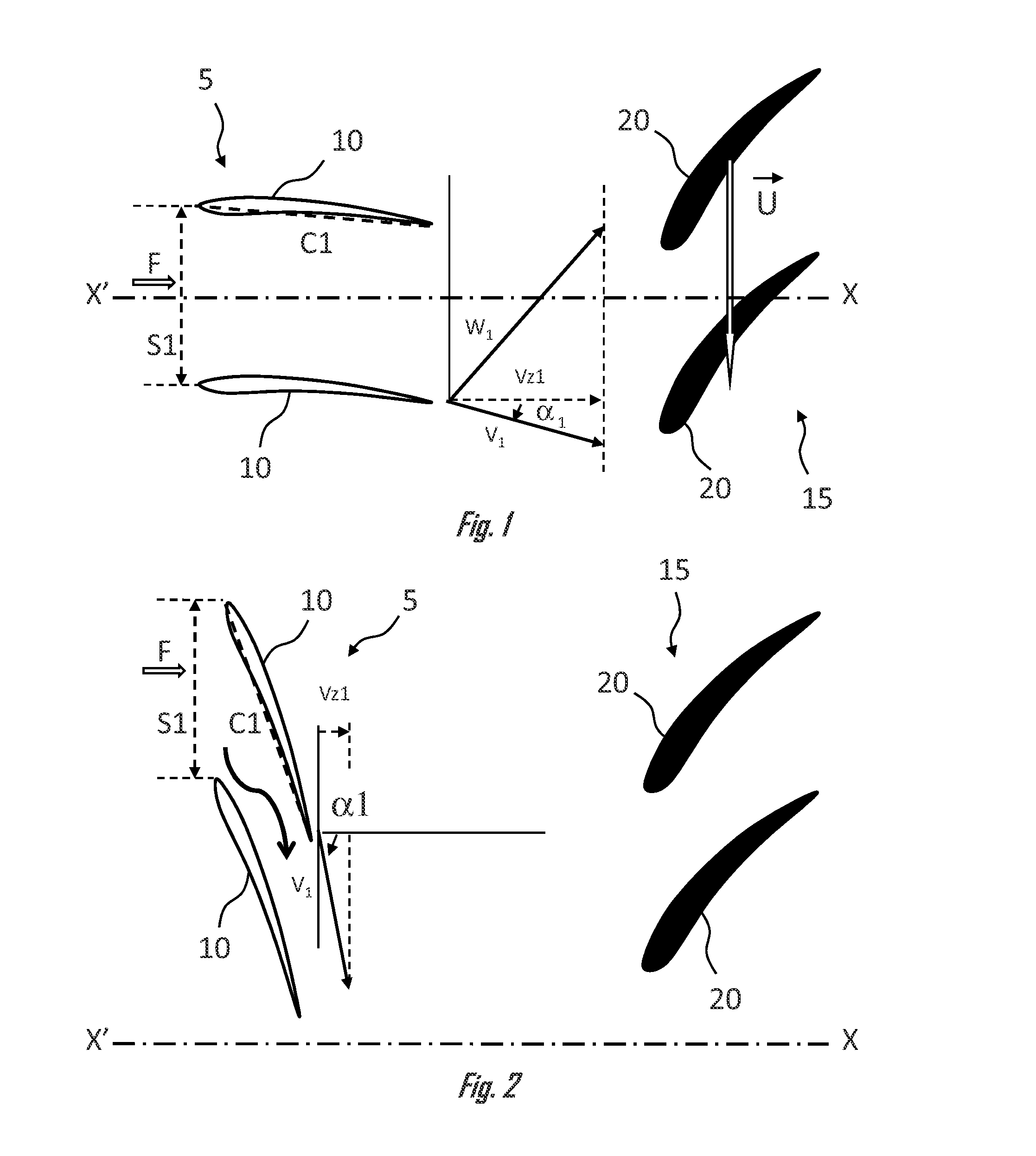
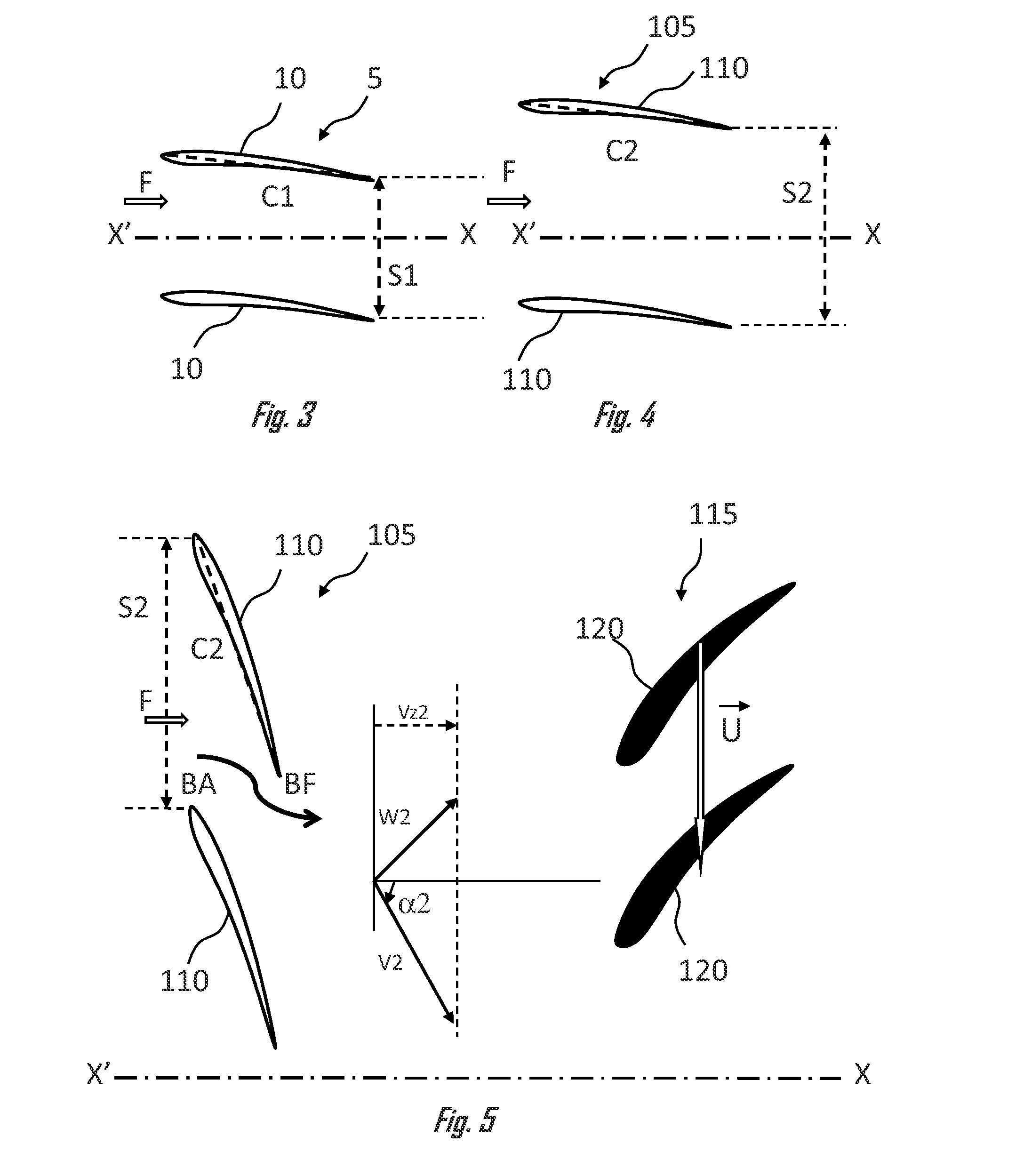
The invention aims to improve the structure of the pre-rotation grille by increasing the pre-rotation angle of the vanes beyond 15° at high operating speeds of the turboshaft engine while preventing aerodynamic malfunctions of the blades of the movable wheel at low operating speeds of the engine. The pitch between the distal ends of two consecutive vanes of the grille is greater than the chord of one vane, which allows the vanes to be used of which the pre-rotation angle is greater than 15° in the upper part of the air duct at high operating speeds and allows efficient aerodynamic operation of the movable compressor wheel at low speeds. The pre-rotation angle of the vanes is between 15° and -25° in the upper part of the air duct, depending on the engine operating speed. This improves the efficiency of the compression stage and prevents aerodynamic malfunctions of the blades of the movable compressor wheel.

Problems solved by technology

Compression assemblies of this type have an aerodynamic stability limit, commonly referred to as a surge line, which in particular limits the acceleration capacity of the turboshaft engine.
At low operating speeds, the aerodynamic stability limit of the compression assembly is linked to an aerodynamic overload of the first compression stage, thereby resulting in too heavy an impact of the air flow reaching the first movable wheel.
In other words, the boundary layers of the air no longer hold to the shape of the head profiles of the blades 20 of the movable wheel 15, and this may cause an aerodynamic stall within the movable wheel 15, which is commonly referred to as a rotating stall, which is detrimental to the aerodynamic stability of the compressor and is therefore a drawback.
However, such an adjustment would reduce the angles of orientation of the air flow for the remainder of the height of the air duct, which is a drawback.

Method used


Image

  • Compression assembly for a turbine engine
  • Compression assembly for a turbine engine
  • Compression assembly for a turbine engine

Examples


Embodiment Construction

[0013]The invention aims to improve the structure of the existing pre-rotation grilles by increasing the pre-rotation angle of the vanes beyond 15° at the top of the air duct at high operating speeds of the turboshaft engine, while preventing aerodynamic malfunctions of the blades of the movable wheel at low operating speeds of the turboshaft engine.

[0014]Although the invention has been developed for an aircraft turboshaft engine, it relates to any compression assembly of a turbine engine comprising a pre-rotation grille, such as that in turboshaft engines, turbojet engines, auxiliary power units (APU), terrestrial turbine engines, turbocompressors, etc. It also relates to any type of compressor, whether it is axial, centrifugal, mixed, etc.

[0015]Therefore, the invention relates to a compression assembly for a turbine engine, in particular a turboshaft engine, said assembly comprising an air inlet duct capable of receiving an air flow, at least one air compression stage comprising a...


PUM


Abstract

Compression assembly for a turbine engine, in particular a turboshaft engine, said assembly comprising an air inlet duct capable of receiving an air flow, at least one air compression stage comprising at least one movable compressor wheel onto which the duct discharges, and a pre-rotation grille which is positioned in the air inlet duct upstream of the movable compressor wheel in order to adjust the speed of the air in said flow at the inlet of the movable wheel and comprises a plurality of variable-setting vanes, the assembly being characterized in that the pitch between two consecutive vanes of the grille is greater than the chord of one of the two vanes at a given height of the air duct, preferably in its upper part.

Description

FIELD OF THE INVENTION[0001]The invention relates to the field of turbine engines, in particular for aircraft. The invention more particularly relates to a compression assembly for a turbine engine, in particular for a helicopter turboshaft engine, and to a turbine engine equipped with an assembly of this type.PRIOR ART[0002]In a known manner, a turboshaft engine comprises a compression assembly comprising an air inlet duct and at least one air compression stage, or compressor, which comprises at least one movable compressor wheel onto which the duct discharges.[0003]Compression assemblies of this type have an aerodynamic stability limit, commonly referred to as a surge line, which in particular limits the acceleration capacity of the turboshaft engine. At low operating speeds, the aerodynamic stability limit of the compression assembly is linked to an aerodynamic overload of the first compression stage, thereby resulting in too heavy an impact of the air flow reaching the first mov...

Claims


Application Information

Patent Timeline
Patent Type & Authority Applications(United States)
IPC IPC(8): F01D7/00F01D9/02F01D1/02
CPCF01D7/00F01D9/02F01D1/02F04D29/544F04D29/563
Inventor ESCURET, JEAN-FRANCOISBISCAY, PIERRESEVESTRE, GUILLAUME
Owner SAFRAN HELICOPTER ENGINES
Learn More