Method and system of oil delivery in a combustion engine

a technology of combustion engine and oil delivery system, which is applied in the direction of machines/engines, mechanical equipment, pressure lubrication, etc., can solve the problems of increasing power consumption and fuel economy, wasting energy, and not providing oil to the piston cooling jet, so as to reduce power consumption and improve fuel economy

Active Publication Date: 2015-10-01
FORD GLOBAL TECH LLC
View PDF4 Cites 18 Cited by
  • Summary
  • Abstract
  • Description
  • Claims
  • Application Information

AI Technical Summary

Benefits of technology

[0008]In this way, oil may be supplied separately to different groups of engine components, the components grouped based on their differing oil pressure and flow requirements, without incurring a loss in hydraulic power. By using separate pumps, each pump may be activated independently based on the lubrication and / or cooling requirements of components coupled to a given pump. Further, the pumps may be simultaneously operated at different speeds and pressures based on existing engine operating conditions and component requirements. As such, this allows each pump to be sized according to the specific output demands made on that pump, enabling a reduction in power consumption and consequently, an improvement in fuel economy. Thus, non-overlapping pressure and flow conditions may be satisfied by grouping components having higher flow and lower pressure lubrication requirements separate from lower flow and higher pressure lubrication requirements, while offering the flexibility to modify pump operation with operating conditions, such as warm-up temperature profiles.

Problems solved by technology

As such, there may be many competing and overlapping demands on an engine oil system during vehicle operation.
However the inventors herein have identified potential issues with the above approaches.
Thus, even though a separate gallery is used to supply oil to piston cooling jets, by using a single, oversized pump, there is an increase in power consumption and a loss in fuel economy.
As another example, even though check valves and control valves may stop or reduce the flow to specific components, a single oil pump may continue to provide oil to a common oil gallery at a pressure requested by the highest requester, resulting in a loss of hydraulic power and a waste of energy.
Thus, during engine operation, the lower pressure pump may supply oil only to piston cooling jets, and may not supply oil to the cylinder head, bearings, the variable valve operation system or a turbocharger.
Simultaneously, the higher pressure pump may deliver oil only to the cylinder head, bearings, the variable valve operation system and / or the turbocharger, and may not provide oil to the piston cooling jets.

Method used


Image

  • Method and system of oil delivery in a combustion engine
  • Method and system of oil delivery in a combustion engine
  • Method and system of oil delivery in a combustion engine

Examples


Embodiment Construction

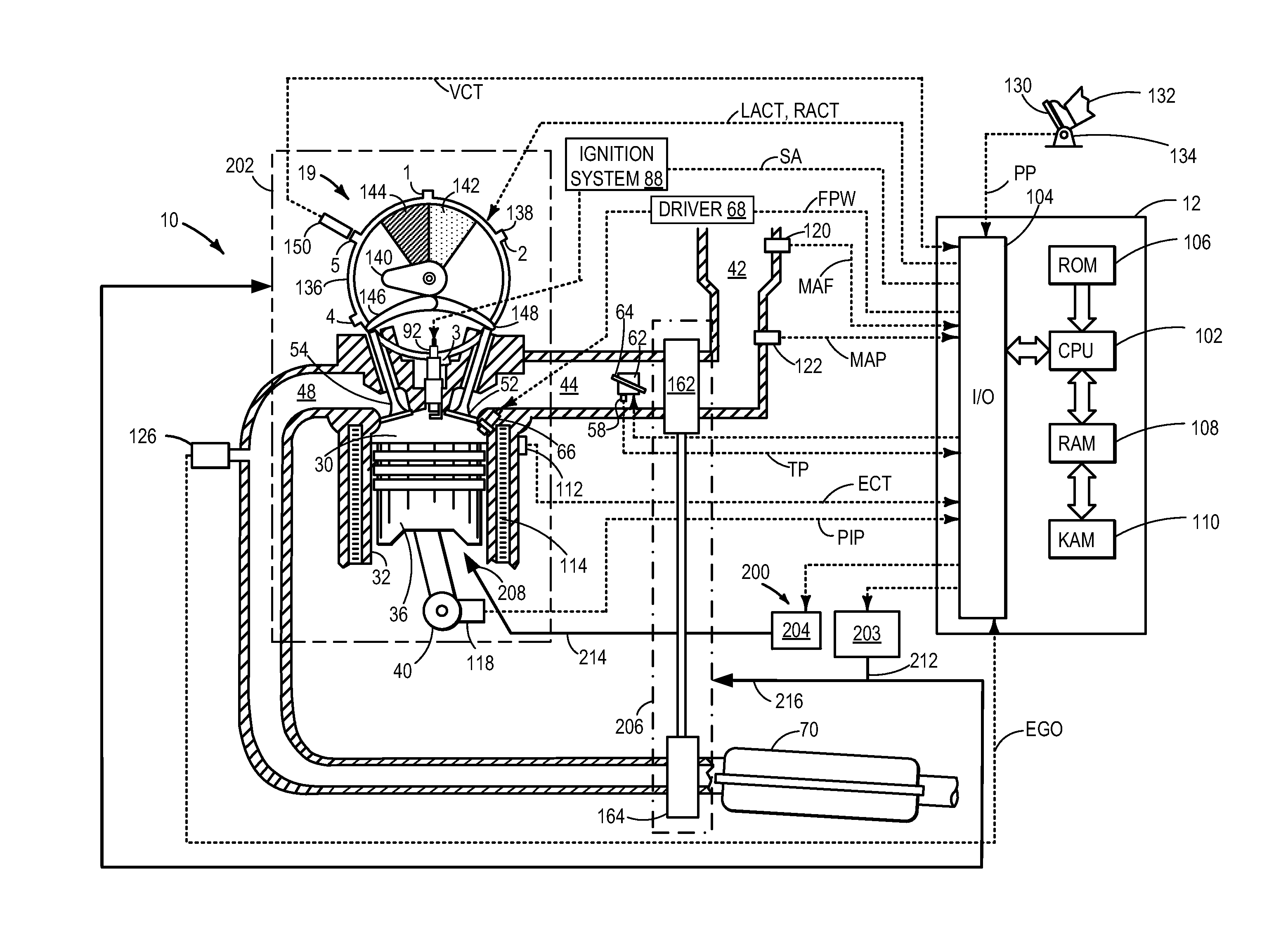
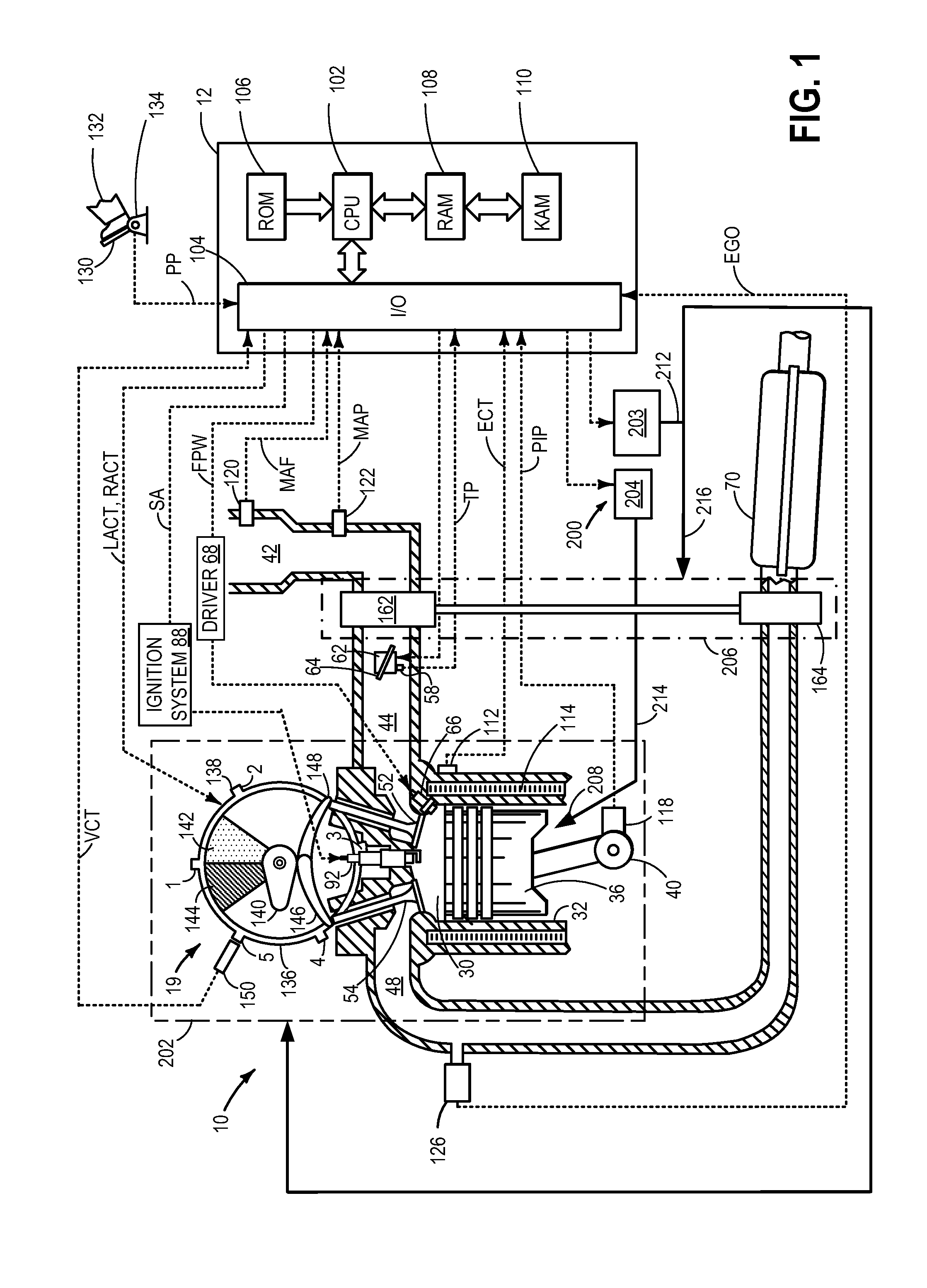
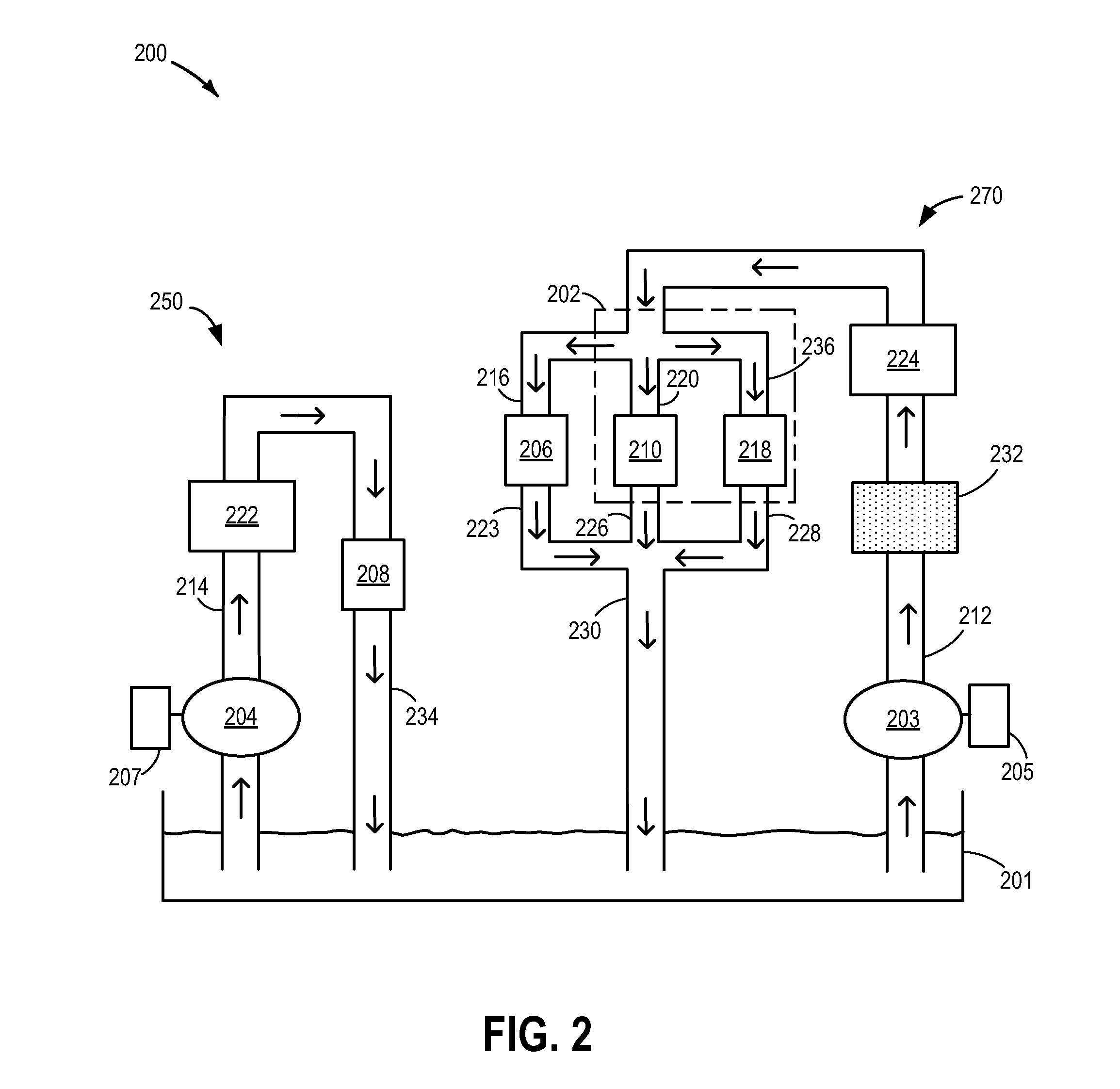
[0016]The following description relates to an oil delivery system for an engine, such as that of FIG. 1, which includes a high pressure circuit and a low pressure circuit wherein, each circuit is coupled to a separate pump. A lower pressure pump, fluidly coupled to the low pressure circuit, selectively pumps oil to piston cooling jets, and a higher pressure pump, fluidly coupled to the high pressure circuit, selectively pumps oil to a cylinder head, bearings, turbocharger, and a variable cam timing system as shown in FIG. 2. A controller may be configured to perform a routine, such as the example routine of FIG. 3, to determine an operating mode for the two pumps based on engine cooling and lubrication requirements. For example, the controller may operate the oil system in a first mode where only the lower pressure pump is operated (FIG. 4), a second mode where only the higher pressure pump is operated (FIG. 5), and a third mode for operating both pumps concurrently. Example pump op...


PUM


Abstract

Methods and systems are described for an oil delivery system of an engine. In one method, oil is pumped via a lower pressure oil pump to piston cooling jets while oil is separately pumped via a higher pressure oil pump to a cylinder head, bearings, a turbocharger, or a variable valve operation system. Herein, the higher and lower pressure oil pumps each draw oil from a common, shared sump, and return oil back to the common, shared sump.

Description

TECHNICAL FIELD[0001]The present application relates to systems and methods for supplying oil in an engine.BACKGROUND AND SUMMARY[0002]Vehicles may use an engine oil system to lubricate and / or cool various components of an internal combustion engine. The oil system for an engine supplies oil from a reservoir, often referred to as a sump, to various components of the engine requiring a supply of oil, such as bearings, hydraulic valve mechanisms, and piston cooling jets.[0003]As such, there may be many competing and overlapping demands on an engine oil system during vehicle operation. For example, different engine components may have different oil flow volume and oil pressure requirements. Further, the oil requirement for a given component may vary depending on operating conditions (e.g., engine load, engine temperature, etc.).[0004]One approach to address the differing oil requirements of the various engine components includes the use of check valves and control valves to modify oil ...

Claims


Application Information

Patent Timeline
Patent Type & Authority Applications(United States)
IPC IPC(8): F01M1/02F01P3/08F01P5/10
CPCF01M1/02F01P3/08F01P5/10F01M1/12F01M2001/086F01M2001/123
Inventor BIDNER, DAVID KARLKOKOTOVIC, VLADIMIR V.
Owner FORD GLOBAL TECH LLC
Why Eureka
Try Eureka