Counterweighting a wind turbine hub

a technology of wind turbine hubs and hubs, which is applied in the direction of propellers, propulsive elements, water-acting propulsive elements, etc., can solve the problems of complex mounting of blades from above the hubs, inability to adjust the depth of the sea, and high installation costs, so as to reduce complexity and cost

Active Publication Date: 2015-10-01
GE RENEWABLE TECH WIND BV
View PDF1 Cites 13 Cited by
  • Summary
  • Abstract
  • Description
  • Claims
  • Application Information

AI Technical Summary

Benefits of technology

[0014]The pitch system may be assisted by some additional drive units, such as e.g. auxiliary gear motors, in causing rotation of the counterweight beam-mass. This may permit providing larger torques to the counterweight beam-mass if needed. If the “standard” pitch system is able to provide large enough torques, using additional drive unit(s) may not be necessary, but may permit relieving the pitch system.
[0049]These methods comprising rotating the nacelle by properly operating the yaw system may be especially advantageous when mounting blades to offshore wind turbines. Working space / conditions in offshore installations are usually very restricted. Hence, the proposed rotation of the nacelle for enabling mounting of different blades in a same right-to-left or left-to-right direction may permit reducing complexity and so reducing costs in this type of offshore operations.

Problems solved by technology

Particularly, in offshore wind turbines, mounting a blade from above the hub may be very complicated, or at least require an enormous crane and jack-up barge.
Such an installation method may thus be very expensive and depending on the depth of the sea may simply be impossible.
But in order to mount a complete rotor assembly, a large surface area is required, which is typically not available in the case of offshore wind turbines.
However, in order to be able to perform these rather complicated installation steps, the prevailing wind speed has to be below a predetermined value, for example 6 or 8 m / s for a prolonged period of time.
During certain seasons, windows of several hours in which the wind does not reach the predetermined value of e.g. 6 m / s may not be available very often.
In practice, this may mean that personnel and maintenance equipment, including e.g. expensive cranes and jack-up barges, may be in stand-by during days or even weeks.
This may represent an enormous cost.
This means that individual installation steps may require less time and may be performed at higher winds, thus increasing the time windows available for installation.
However, such methods require rotation of the hub between the mounting of one blade and another.
This is not possible in case of directly driven wind turbines as no gearbox is provided between rotor and generator.
Even though the generator may be suitable for being operated as a motor, it will generally not be able to deliver the required torque to rotate the hub when the hub is unbalanced, i.e. when at least one but not all the blades have been mounted.

Method used


Image

  • Counterweighting a wind turbine hub
  • Counterweighting a wind turbine hub
  • Counterweighting a wind turbine hub

Examples


Embodiment Construction

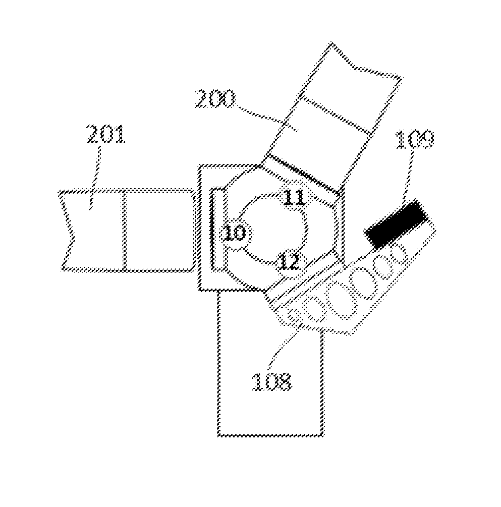
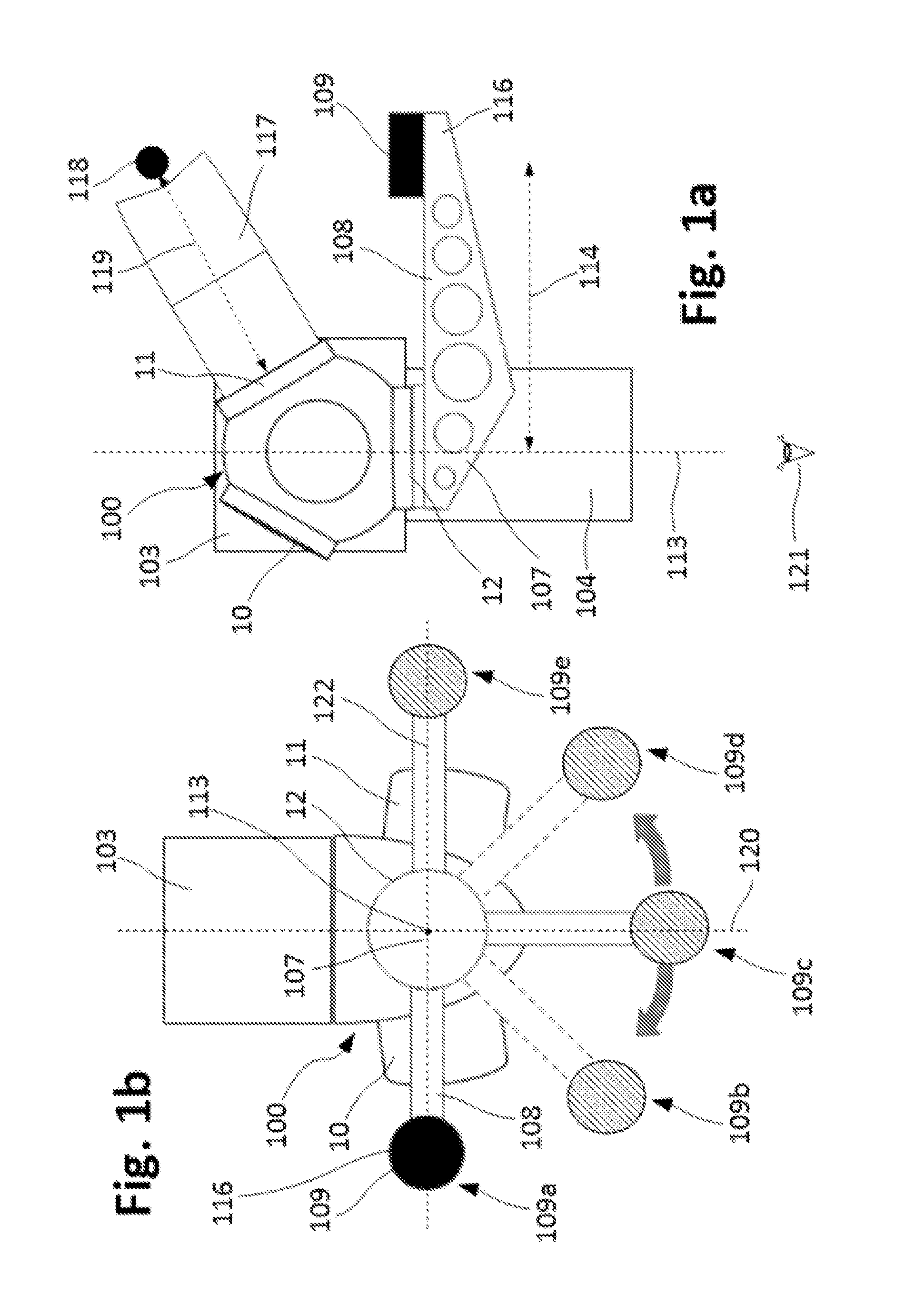
[0055]FIGS. 1a-1b schematically represent a front view and a bottom view of a counterweight system according to an example, said counterweight system being mounted to a hub 100 of a wind turbine. FIG. 1a shows said front view. FIG. 1b shows said bottom view from a point of vision 121 shown in FIG. 1a.

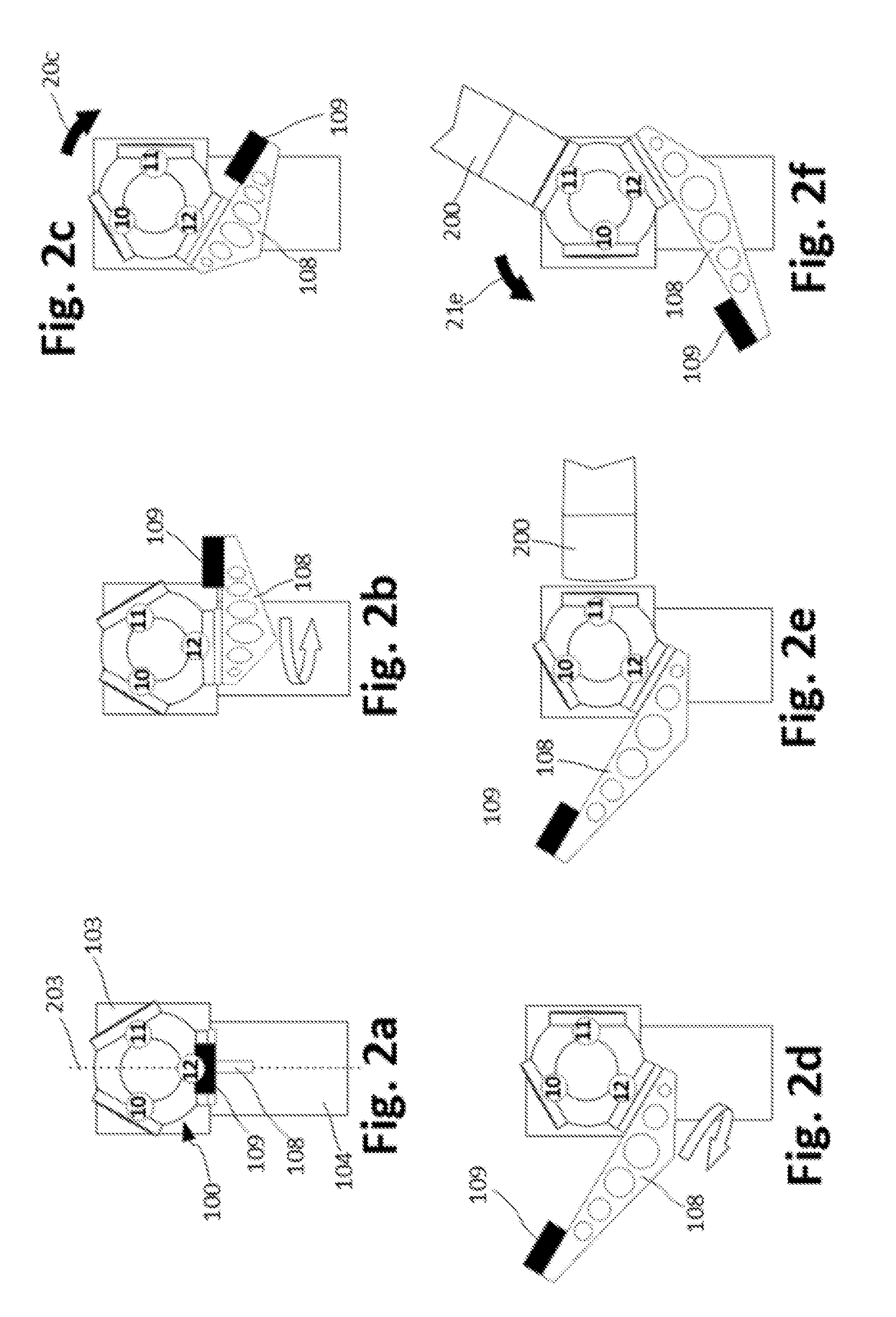
[0056]The wind turbine is shown having a tower 104, a nacelle 103 mounted on the tower 104, and a hub 100 mounted to the nacelle 103. The hub 100 is mounted to the nacelle 103 in such a way that the hub 100 is rotatable around a rotation axis 120 with respect to the nacelle 103. The hub 100 is shown comprising a first region 11 adapted to receive a blade root, a second region 12 adapted to receive a blade root, and a third region 10 adapted to receive a blade root. Each of these regions 10, 11, 12 may comprise a pitch system (not shown) for rotating a blade to be mounted to said region 10, 11, 12. Said rotation may be about a pitch axis 113, i.e. a longitudinal axis of the blade when m...


PUM

PropertyMeasurementUnit
massaaaaaaaaaa
rotationaaaaaaaaaa
distanceaaaaaaaaaa

Abstract

Counterweight systems for a wind turbine comprising a hub mounted to a nacelle such that the hub is rotatable around a rotation axis with respect to the nacelle, the hub comprising a blade root region configured to receive a root of a blade and having a pitch system configured to rotate the blade around a pitch axis. The counterweight system comprises a beam mountable to the blade root region at a first point of the beam and a counterweight mass coupled to the beam at a second point of the beam, such that, when the beam is mounted to the blade root region, the beam is arranged substantially perpendicular to the pitch axis and the pitch system can cause the counterweight mass to rotate around the pitch axis. Methods are also provided of mounting one or more blades to a wind turbine hub by using such counterweight systems.

Description

[0001]This application claims priority to EP Application No. 14382117.1 filed Mar. 28, 2014, the entire contents of which are hereby incorporated by reference.[0002]The present disclosure relates to counterweight systems for a wind turbine hub, and to methods of mounting a blade to a wind turbine hub by using one of such counterweight systems.BACKGROUND[0003]Modern wind turbines are commonly used to supply electricity into the electrical grid. Wind turbines generally comprise a rotor with a rotor hub and a plurality of blades. The rotor is set into rotation under the influence of the wind on the blades. The rotation of a rotor shaft drives a generator rotor either directly (“directly driven”) or through the use of a gearbox. The gearbox (if present), the generator and other systems are usually mounted in a nacelle on top of a wind turbine tower.[0004]When wind turbines are erected, the tower is generally constructed first. Then the nacelle, which typically contains the generator and...

Claims


Application Information

Patent Timeline
Patent Type & Authority Applications(United States)
IPC IPC(8): F03D1/00F03D7/02
CPCF03D7/0224F03D1/001F03D80/00F03D1/0658Y10T29/49316F03D13/10Y02E10/72F03D15/20
Inventor CANEDO PARDO, SANTIAGO
Owner GE RENEWABLE TECH WIND BV
Why Eureka
Try Eureka