
Optical test apparatus

a test apparatus and optical technology, applied in the field of optical test apparatus, can solve the problems of large size and complexity of the simulator described in the patent literature, and achieve the effect of simplifying the configuration and reducing the size of the optical test apparatus

Active Publication Date: 2015-10-01
MITSUBISHI HEAVY IND LTD
View PDF3 Cites 11 Cited by
  • Summary
  • Abstract
  • Description
  • Claims
  • Application Information

AI Technical Summary

Benefits of technology

The present invention provides an optical test apparatus that is smaller, easier to handle, and has a simpler configuration, making it less prone to failures. This is possible because the physical movement of the simulated target source is unnecessary.

Problems solved by technology

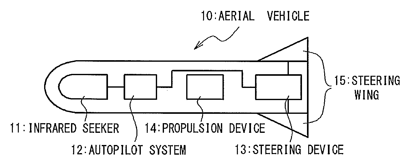
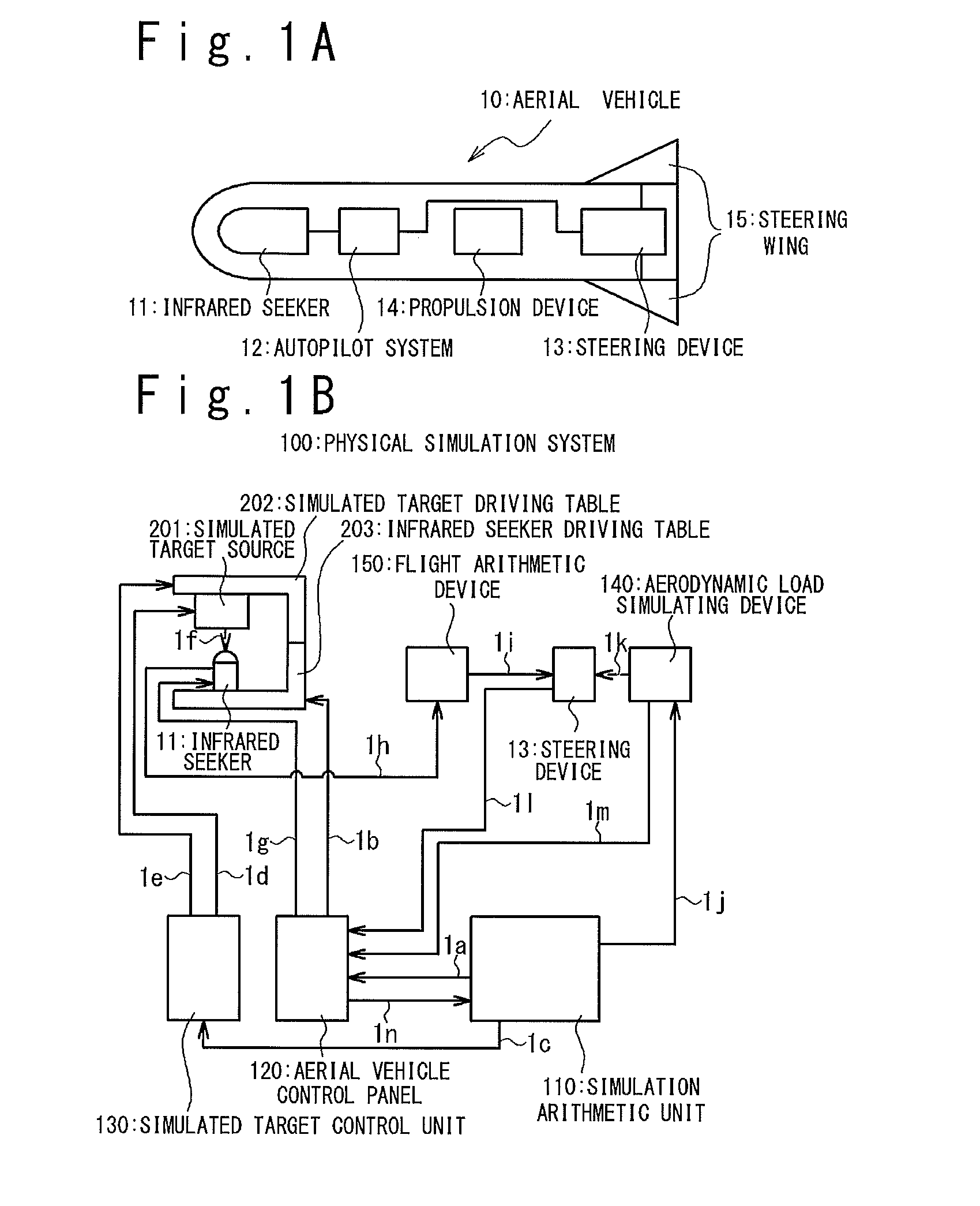
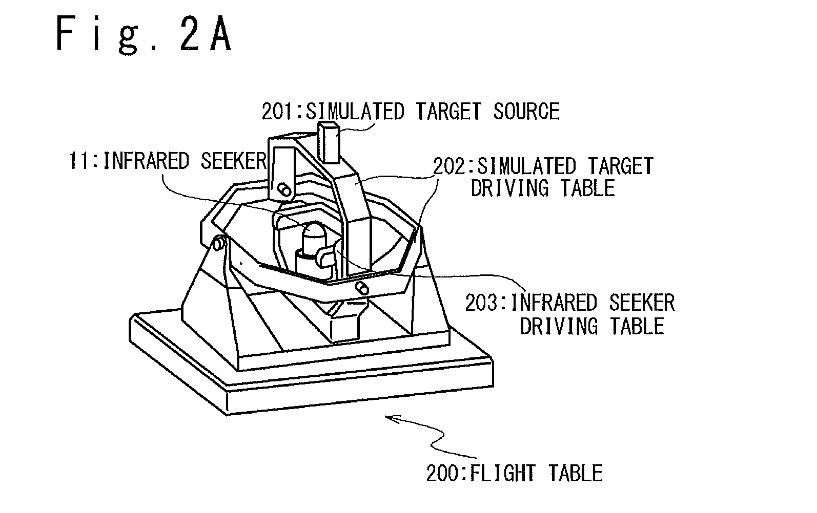
However, the simulator described in the Patent Literature 1 is still complex and has a large-size.

Method used


Image

  • Optical test apparatus
  • Optical test apparatus
  • Optical test apparatus

Examples


first embodiment

[0047]FIG. 4A is a block diagram of an optical test apparatus according to a first embodiment. Components of the optical test apparatus shown in FIG. 4A will be explained. The optical test apparatus shown in FIG. 4A includes a simulation arithmetic unit 410, an aerial vehicle control panel 420 (i.e. a second control unit 420), a simulated target control unit 430 (i.e. a first control unit 430), an aerodynamic load simulating device 440, a flight arithmetic device 450 (i.e. a flight command calculating device 450), a simulated target image generating device 500 and an infrared seeker driving table 403 (i.e. an infrared seeker driving mechanism 403).

[0048]The optical test apparatus shown in FIG. 4A is the same as the physical simulation apparatus 100 shown in FIG. 1B with the assembly of the simulated target 201 and the simulated target driving table 202 replaced by the simulated target image generating device 500 shown in FIG. 4A.

[0049]In other words, the simulation arithmetic unit 4...

second embodiment

[0063]The heat source generating the infrared light is used as the light source according to the first embodiment. However, it is possible to use another type of light source. An alternative example according to the second embodiment will be explained.

[0064]FIG. 6 is a schematic diagram for indicating a configuration example of light sources according to the second embodiment. Components of the light sources shown in FIG. 6 will be explained. The light sources shown in FIG. 6 include a plurality of collimators 601, a plurality of optical fibers 602, and a plurality of light-emitting elements 603. Note that each of the plurality of light-emitting elements 603 may be, for example, an infrared laser oscillation device, LED (Light Emitting Diode), etc.

[0065]Connection relationship among the components shown in FIG. 6 will be explained. The plurality of collimators 601, the plurality of optical fibers 602 and the plurality of light emitting elements 603 are connected (optically connected...


PUM


Abstract

An optical test apparatus includes a three-dimensional dome, light sources and a control unit. The three-dimensional dome covers a field of view of an image acquisition device. The image acquisition device is a test target device. The light sources are dispersedly arranged on the three-dimensional dome and generate a predetermined image on the three-dimensional dome. The first control unit controls the light sources.

Description

CROSS REFERENCE[0001]This application claims a priority based on Japan Patent Application No. JP 2014-74465 filed on Mar. 31, 2014, the disclosure of which is hereby incorporated by reference herein in its entirety.TECHNICAL FIELD[0002]The present invention relates to an optical test apparatus, and can be used for testing, for example, an image acquisition device such as an infrared seeker of an aerial vehicle.BACKGROUND ART[0003]Patent Literature 1 discloses a simulator having characteristics described below. The simulator includes a database section, a simulation setting section, a target simulated light emitting section, a target light source controlling section, a simulated target unit, a simulated movement driving section, a simulated movement controlling section, a dome, a target detection device, a test target system, a measuring section for measuring an atmospheric transmittance in the dome, and a correction data processing section. Note that the database section stores data...

Claims


Application Information

Patent Timeline
Patent Type & Authority Applications(United States)
IPC IPC(8): F42B15/08H04N7/18H04N5/33F42B15/01
CPCF42B15/08H04N5/33H04N7/183F42B15/01F42B35/00H04N17/002F41G7/004G01S3/7803
Inventor SATO, MARIKOFURUYA, SHOJIROMIYOSHI, DAICHIHATA, YUKITO
Owner MITSUBISHI HEAVY IND LTD
Learn More