
Method and device for detecting deviations of an object surface

a technology for object surfaces and deviations, applied in the direction of image data processing, electrical/magnetic measurement arrangements, using electrical/magnetic means, etc., can solve the problems of requiring a great deal of setup effort, enabling detecting shape deviations, and method only providing useful results on selected geometries, so as to simplify the processing of very large surfaces and avoid gaps and irregularities.

Active Publication Date: 2015-10-01
INB VISION
View PDF4 Cites 8 Cited by
  • Summary
  • Abstract
  • Description
  • Claims
  • Application Information

AI Technical Summary

Benefits of technology

This patent describes a method and device for identifying differences in the surface of an object by comparing measured data to pre-specified reference data. The goal is to provide a reliable and affordable way to detect small deviations in surface quality. This technology is simple and cost-effective to implement and can be used in a variety of applications.

Problems solved by technology

However, in the known methods, it is disadvantageous that the measurement results so obtained depend greatly on the illumination and camera arrangements relative to the surface of the component—that is, they require a great deal of effort to be set-up.
Moreover, the known methods are only suitable for large, relatively flat surfaces with minimal curvature, and the surfaces must additionally be convex.
However, this approach only enables detecting shape deviations with a large extension, or deviations from the theoretical construction data.
However, this known method only provides useful results on selected geometries.
It is disadvantageous in this case that an extremely large volume of data is created for the model of the reference part due to the artificial neural network.
If only sub-areas of the entire surface of the object are measured, the data volume is reduced, but this leads to gaps at each of the transition zones, such that these transition zones cannot be appropriately analyzed.
Finally, it is an additional disadvantage that an error detection is oriented to a global coordinate system, and it is not possible to take into account small local curvatures of the surface.

Method used


Image

  • Method and device for detecting deviations of an object surface
  • Method and device for detecting deviations of an object surface
  • Method and device for detecting deviations of an object surface

Examples


Embodiment Construction

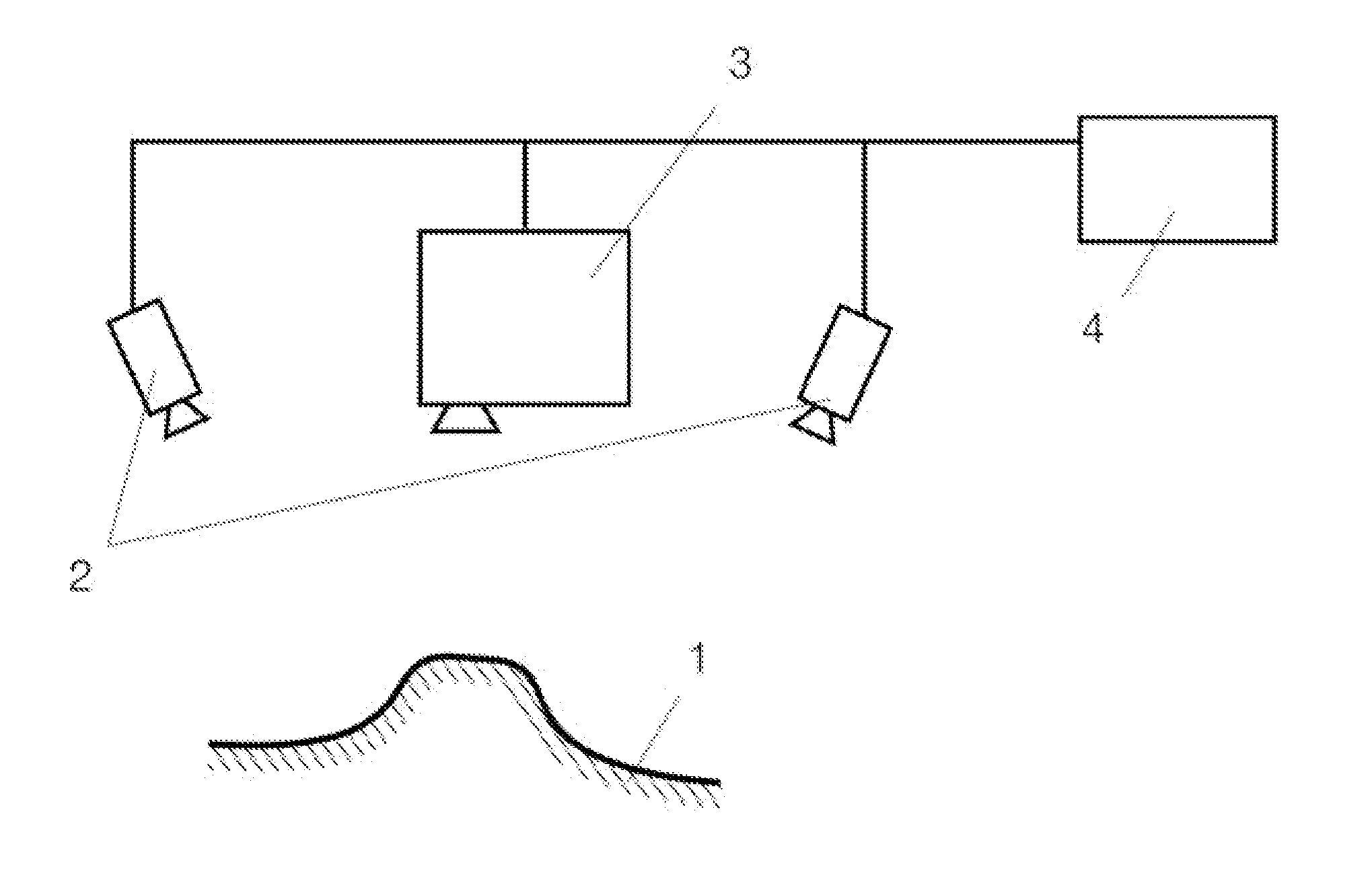
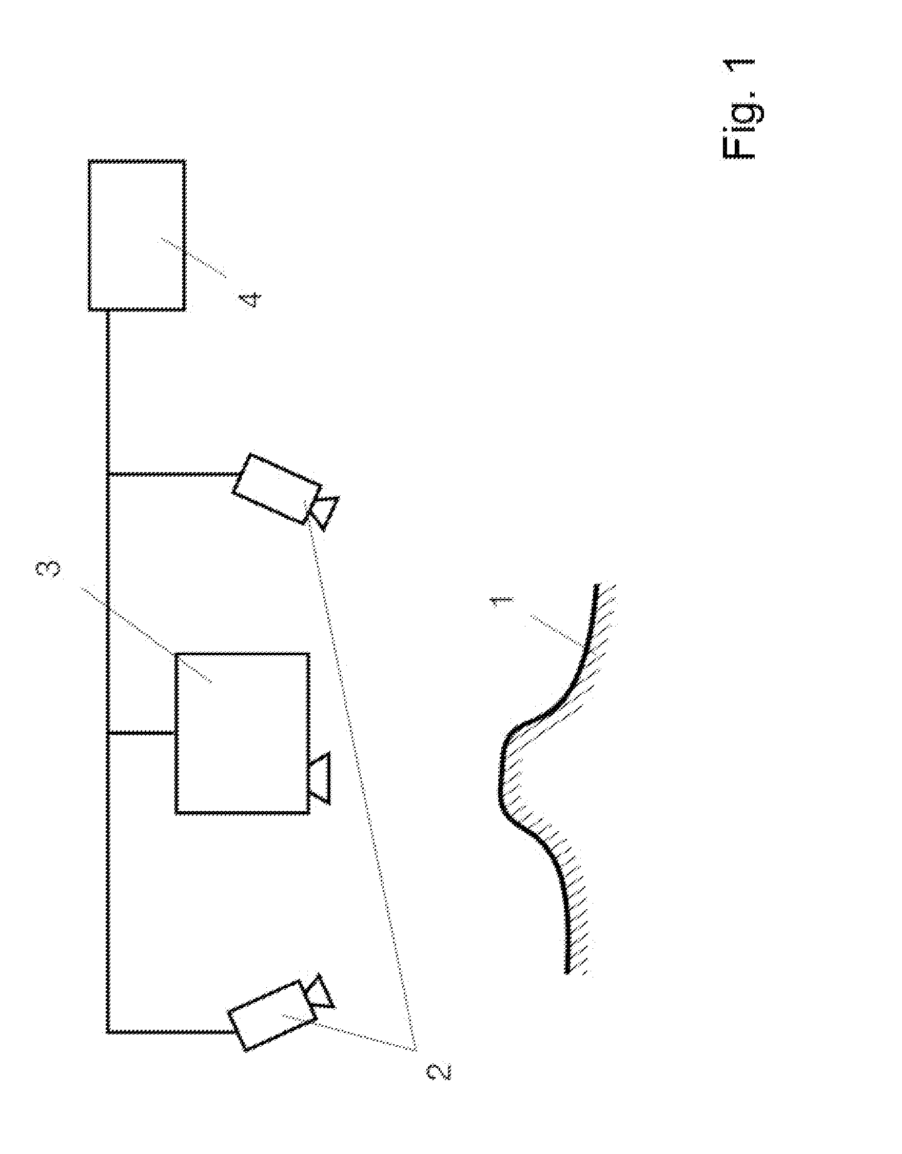
[0043]FIG. 1 shows a schematic view, in part, of one embodiment of the fundamental arrangement of a device according to the invention, which uses the method according to the invention.

[0044]FIG. 1 shows a surface of an object being measured, with reference number 1. In addition, two cameras 2 and a projector 3 are arranged between the two cameras 2. Both the cameras 2 and the projector 3 are connected to a processing and control device 4 which controls the cameras and the projector. In order to measure the surface 1, the projector 3 projects a sine-shaped stripe pattern onto the surface 1 which is shifted in certain chronological steps by a certain phase difference. The surface 1 is captured by the cameras 2 with each projected pattern, such that a sequence of images is created in each case with a certain chronological sequence of grayscale values. The cameras 2 transmit the captured images to the processing and control device 4 such that the processing and control device 4 can find...


PUM


Abstract

The invention relates to a method for detecting deviations of an object surface using a comparison between measured data of the surface and specified reference data. A surface description, at least portions of which are parametric, is generated as a target surface model using the specified reference data, and the comparison is carried out using the target surface model and the measured data. The invention likewise relates to a device for detecting deviations of an object surface using a comparison between measured data of the surface and specified reference data.

Description

CROSS REFERENCE TO RELATED APPLICATIONS[0001]This application is a national stage application, filed under 35 U.S.C. §371, of International Application No. PCT / DE2013 / 200076 filed Jul. 25, 2013, which claims priority to German Application No. 10 2012 215 195.8 filed Aug. 27, 2012 and German Application No. 10 2012 215 215.6 filed Aug. 28, 2012, the contents of both of which as are hereby incorporated by reference in their entirety.BACKGROUND[0002]1. Technical Field[0003]The invention relates to a method for recognizing deviations in a surface of an object using a comparison of measured data of the surface and prespecified reference data.[0004]The invention also relates to a device for recognizing deviations in a surface of an object using a comparison of measured data of the surface and prespecified reference data, particularly suitable for carrying out a method according to one of the claims.[0005]The term “surface” should be understood in the broadest possible sense, including bot...

Claims


Application Information

Patent Timeline
IPC IPC(8): G01B21/30
CPCG01B21/30G01B21/04G01B21/20G06T17/30G01B21/047
Inventor MICHAELIS, BERNDLILIENBLUM, TILOVON ENZBERG, SEBASTIAN
Owner INB VISION
Learn More