Active liquid crystal diffraction element and phase-modulating holographic display

a liquid crystal diffraction element and phase-modulating technology, applied in the direction of instruments, active addressable light modulators, hologram nature/properties, etc., can solve the problems of unstable diffraction efficiency, difficult to obtain stable diffraction efficiency, and undesirable diffraction optical elements to exhibit unstable and asymmetric features

Inactive Publication Date: 2015-10-01
SHARP KK +1
View PDF4 Cites 4 Cited by
  • Summary
  • Abstract
  • Description
  • Claims
  • Application Information

AI Technical Summary

Benefits of technology

[0008]The present invention is made in light of the problems described above. An object of the present invention is to provide an active liquid crystal diffraction element and a phase-modulating holographic display exhibiting stable and symmetric features by preventing liquid crystal molecular alignment from being pre-tilted.
[0015](7) The active liquid crystal diffraction element described in (6) may be configured as follows: the control member reduces the period of the electric voltage applied to the second electrode in order to converge the incident light.
[0021]According to the configurations described in (1), the alignment member confers a liquid crystal molecular alignment without any pre-tilt to the liquid crystal layer. As a result, it is possible to obtain an active liquid crystal diffraction element that exhibits stable and symmetric characteristics.
[0022]According to the configurations described in (2), (3), (4), and (5), the liquid crystal layer includes a photo-sensitive alignment film. Photo-alignment technology may be employed to create an alignment of the liquid crystal molecules of the liquid crystal layer. As a result, it is possible to prevent any pre-tilts from occurring. Therefore, it is possible to obtain an active liquid crystal diffraction element that exhibits stable and symmetric characteristics.
[0028]According to the configurations described in (11), the phase-modulating holographic display (301) includes two active liquid crystal diffraction elements as described in (1), and one of them exhibit features of a lens. As a result, it is possible to conduct a tracking operation in the x-axis direction, the y-axis direction, and the z-axis direction.

Problems solved by technology

However, when a liquid crystal layer having an anti-parallel alignment is used in the diffraction optical element 101 disclosed in Patent Literature 1, for example, it becomes difficult for the diffraction optical element 101 to exhibit axisymmetric features. FIG. 9 illustrates this problem.
As a result, it becomes difficult to obtain a stable diffraction efficiency.
Since diffraction optical elements are used to control the direction of light, it is undesirable for diffraction optical elements to exhibit unstable and asymmetric features.
Pre-tilts in liquid crystal layers cause such unstable and asymmetric features.

Method used


Image

  • Active liquid crystal diffraction element and phase-modulating holographic display
  • Active liquid crystal diffraction element and phase-modulating holographic display
  • Active liquid crystal diffraction element and phase-modulating holographic display

Examples


first embodiment

[0042]An active liquid crystal diffraction element according to a First Embodiment of the present invention is described with reference to FIGS. 1 through 5.

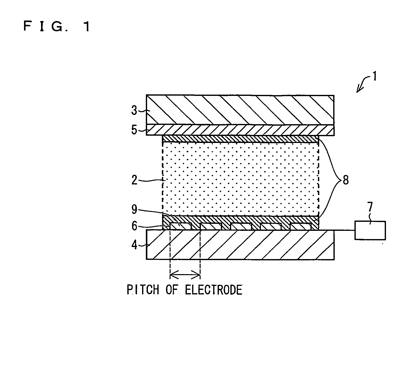
[0043]FIG. 1 is a cross sectional diagram showing a configuration of an active liquid crystal diffraction element 1 according to the present embodiment. The active liquid crystal diffraction element 1 is an optical deflector element using liquid crystal. This active liquid crystal diffraction element 1 includes a liquid crystal layer 2, a first transparent substrate 3, a second transparent substrate 4, a first electrode 5, a second electrode 6, a control member 7, and a photo-alignment member 8.

[0044]The liquid crystal layer 2 is provided between the first transparent substrate 3 and the second transparent substrate 4. The first transparent substrate 3 and the second transparent substrate 4 are each processed with anti-reflective coating. The first transparent substrate 3 may be a glass substrate. The second transparent substrat...

second embodiment

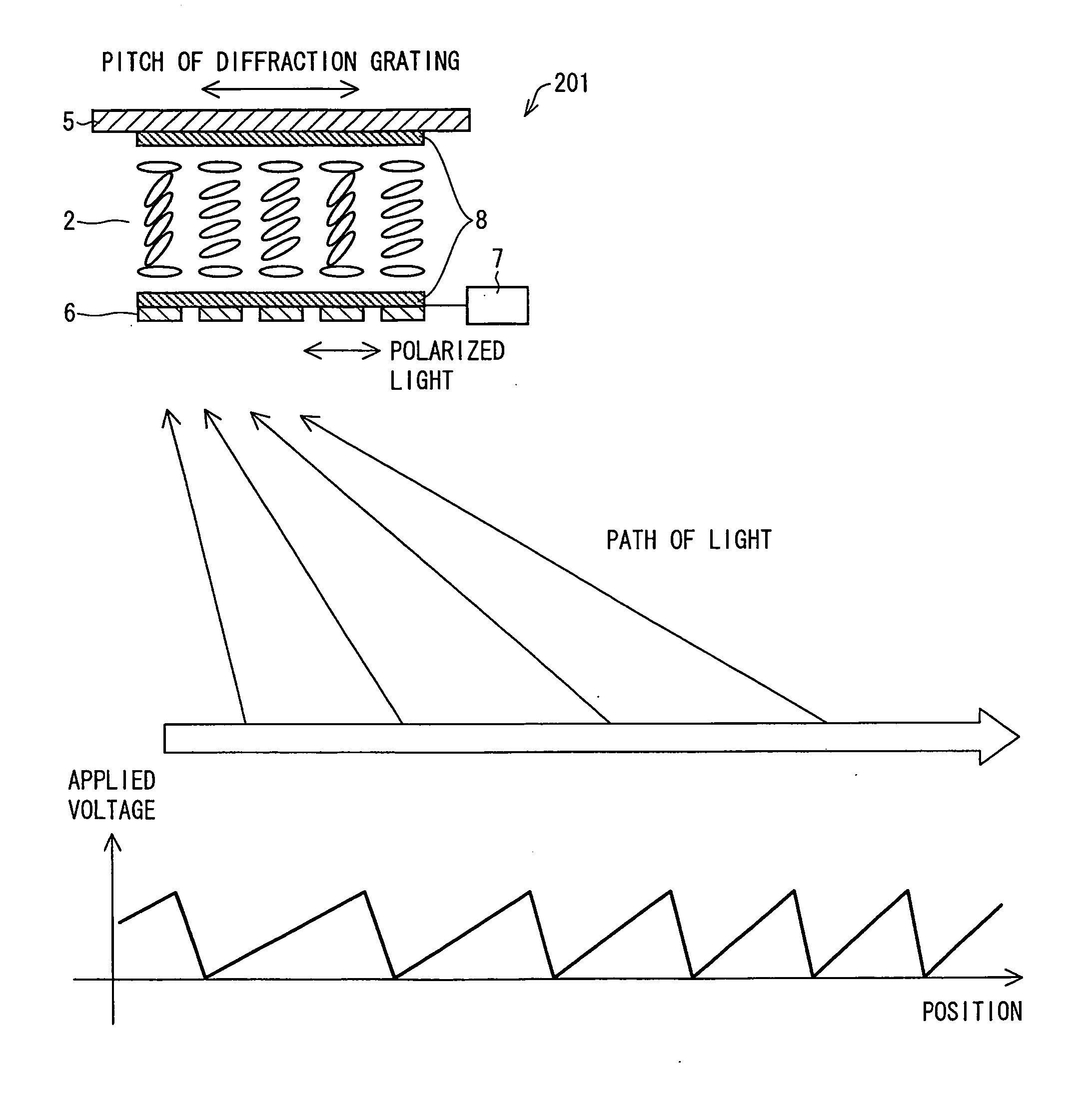
[0058]Next, an active liquid crystal diffraction element according to a Second Embodiment of the present invention is described with reference to FIG. 6. Incidentally, the components which act in the same manner as the components described in the First Embodiment are referred to using the same reference numerals. Descriptions of components already described in the First Embodiment may be omitted in the present Second Embodiment.

[0059]An active liquid crystal diffraction element 201 according to the present embodiment includes a includes a liquid crystal layer 2, a first transparent substrate 3, a second transparent substrate 4, a first electrode 5, a second electrode 6, a control member 7, and a photo-alignment member 8. The control member 7 controls the electric voltage applied to the second electrode 6 so that the pitch of the diffraction grating may be adjusted.

[0060]FIG. 6 shows an example of how the electric voltage applied to the second electrode 6 is controlled. FIG. 6 also s...

third embodiment

[0062]Next, an embodiment of a phase-modulating holographic display 301 according to a Third Embodiment of the present invention is described with reference to FIG. 7. Incidentally, the components which act in the same manner as the components described in the First Embodiment and / or the Second Embodiment are referred to using the same reference numerals. Descriptions of components already described in the First Embodiment and / or the Second Embodiment may be omitted in the present Third Embodiment.

[0063]FIG. 7 shows a configuration of a phase-modulating holographic display 301 according to the present embodiment. This phase-modulating holographic display 301 includes a laser light source 302, a liquid crystal panel (SLM: Spacial Light Modulator) 303, a patterning retardation film 304, a beam combiner 305, a polarizer 306, a retardation film 307, and a liquid crystal diffraction grating 308.

[0064]The liquid crystal diffraction grating 308 includes the active liquid crystal diffractio...


PUM

PropertyMeasurementUnit
widthaaaaaaaaaa
wavelengthaaaaaaaaaa
electric voltageaaaaaaaaaa

Abstract

An active liquid crystal diffraction element includes: a first transparent substrate; a second transparent substrate; a liquid crystal layer; a first electrode; a second electrode; a control member; and an alignment member, wherein the second electrode includes a plurality of small electrodes; the control member controls a magnitude of an electric voltage applied to each of the plurality of small electrodes; the alignment member confers a liquid crystal molecular alignment without any pre-tilt to the liquid crystal layer; and the liquid crystal molecular alignment is parallel to the surface of the first transparent substrate.

Description

TECHNICAL FIELD[0001]The present invention relates to an active liquid crystal diffraction element which employs photo-alignment technology to control liquid crystal molecule alignment without creating any pre-tilts. The present invention also relates to a phase-modulating holographic display.BACKGROUND ART[0002]Liquid crystal diffraction elements can control the direction of light. As an example of such a liquid crystal diffraction element, Patent Literature 1 (Japanese Unexamined Patent Publication Bulletin No. 2003-43234 (Publication Date: Feb. 13, 2003)) discloses a diffraction optical element 101. FIG. 8 is a perspective diagram showing a configuration of this diffraction optical element 101. The diffraction optical element 101 includes a first transparent substrate 102, a second transparent substrate 103, a liquid crystal layer 104, and a plurality of transparent electrodes 105. The liquid crystal layer 104 is sandwiched between the first transparent substrate 102 and the seco...

Claims


Application Information

Patent Timeline
Patent Type & Authority Applications(United States)
IPC IPC(8): G02F1/139G02F1/29G03H1/22G02F1/1337
CPCG02F1/1393G02F1/1337G02F1/133788G02F1/292G03H2225/36G02F2001/133738G03H2225/22G03H2225/32G03H2225/60G03H1/2294G02F1/13471G02F1/141G02F2203/24G02F2203/28G03H2001/0224G03H2240/42G02F1/133738
Inventor USUKURA, NARUKANBAYASHI, YUUICHIKATOH, HIROMILEISTER, NORBERT
Owner SHARP KK
Why Eureka
Try Eureka