

Image forming apparatus
- Summary
- Abstract
- Description
- Claims
- Application Information
AI Technical Summary
Benefits of technology
Problems solved by technology
Method used
Image

Examples
embodiment 1
(1) Overall Structure and Operation of Image Forming Apparatus
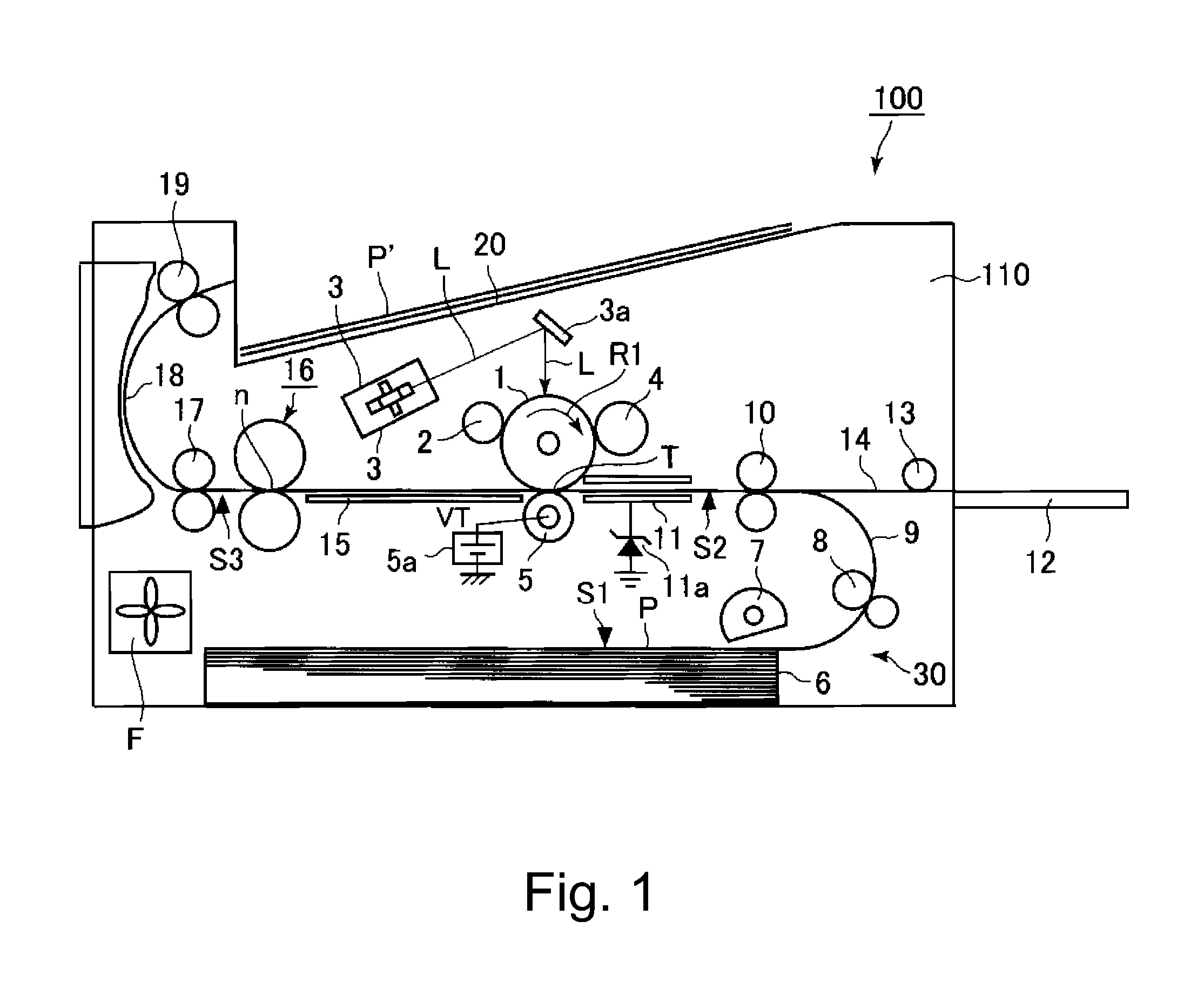
[0028]FIG. 1 is a schematic sectional view of the image forming apparatus in the first embodiment of the present invention. The image forming apparatus 100 in this embodiment is a laser beam printer which uses an electrophotographic process of the so-called transfer type. This image forming apparatus 100 receives image formation data (printing data) from a host computer, and develops the data into image information (dot map). Then, it forms an image on a sheet P of recording medium with the use of its electrophotographic engine section, which is in its main assembly 110, based on the image information. Here, a sheet P of recording medium may be referred to as a sheet P of ordinary paper. However, this embodiment is not intended to limit the present invention in scope in terms of recording medium.
[0029]The electrophotographic engine section is provided with an electrophotographic photosensitive member (photosensitive drum...
embodiment 2
[0072]Next, another embodiment of the present invention is described. The image forming apparatus 100 in this embodiment is the same in basic structure and operation as the image forming apparatus 100 in the first embodiment. Therefore, the components of the image forming apparatus 100 in this embodiment, which are the same as, or equivalent to, the counterparts in the first embodiment, in function and structure, are given the same referential codes as the counter parts, and are not described in detail.
[0073]This embodiment is characterized in that the threshold value X for the difference ΔVtn is adjusted according to the electrical resistance (which hereafter may be referred to as initial electrical resistance) of the pressure roller 24 measured before a printing operation is started (more precisely, during pre-rotation process).
[0074]FIG. 6 shows the changes which occurred to the electrical resistance of the transfer roller 5 while 500 prints were continuously made on moist sheets...
embodiment 3
[0079]Next, another embodiment of the present invention is described. The basic structure and operation of the image forming apparatus 100 in this embodiment are the same as those of the image forming apparatus 100 in the first embodiment. Therefore, the components of the image forming apparatus in this embodiment, which are the same as, or similar to, the counterparts in the first embodiment, in terms of function and operation, are given the same referential codes as the counterparts, and are not described in detail.
[0080]This embodiment is characterized in that the threshold value X for the difference ΔVtn is adjusted according to the water content of the transfer roller 5 measured before a printing operation is started (more precisely, during pre-rotation process in printing operation).
[0081]Whether the transfer roller 5 is relatively high or low in water content prior to the starting of a printing operation significantly affects the change which occurs to the electrical resistan...
PUM
 Abstract
Description
Claims
Application Information