Image processing apparatus, image processing method, and medium

a technology of image processing and image processing medium, applied in the field of image processing, can solve the problems of increasing computational costs or lacking physical accuracy of conventional technologies, and achieve the effect of eliminating the influence of the shape of each local region, increasing computational costs, and lacking physical accuracy

Active Publication Date: 2015-10-01
CANON KK
View PDF8 Cites 8 Cited by
  • Summary
  • Abstract
  • Description
  • Claims
  • Application Information

AI Technical Summary

Benefits of technology

[0008]However, the conventional technologies have the problems of increasing computational costs or lacking physical accuracy because of additionally involving a shaping process due to the fact that the transmittance distribution reflects the shape of each local region. To eliminate the influence of the shape of each local region on the transmittance distribution, for example, U.S. Pat. No. 8,340,461 discloses that soft matting is necessary; Japanese Patent Laid-Open No. 2012-221237, a noise elimination process for transmittance; and Japanese Patent No. 4807439, a smoothing process.
[0009]Therefore, an object of the present invention is to generate a restored image with higher accuracy at less computational cost by eliminating a division into local regions.
[0011]The present invention achieves the advantageous effect of generating a restored image with higher accuracy at less computational cost.

Problems solved by technology

However, the conventional technologies have the problems of increasing computational costs or lacking physical accuracy because of additionally involving a shaping process due to the fact that the transmittance distribution reflects the shape of each local region.

Method used


Image

  • Image processing apparatus, image processing method, and medium
  • Image processing apparatus, image processing method, and medium
  • Image processing apparatus, image processing method, and medium

Examples


embodiment 1

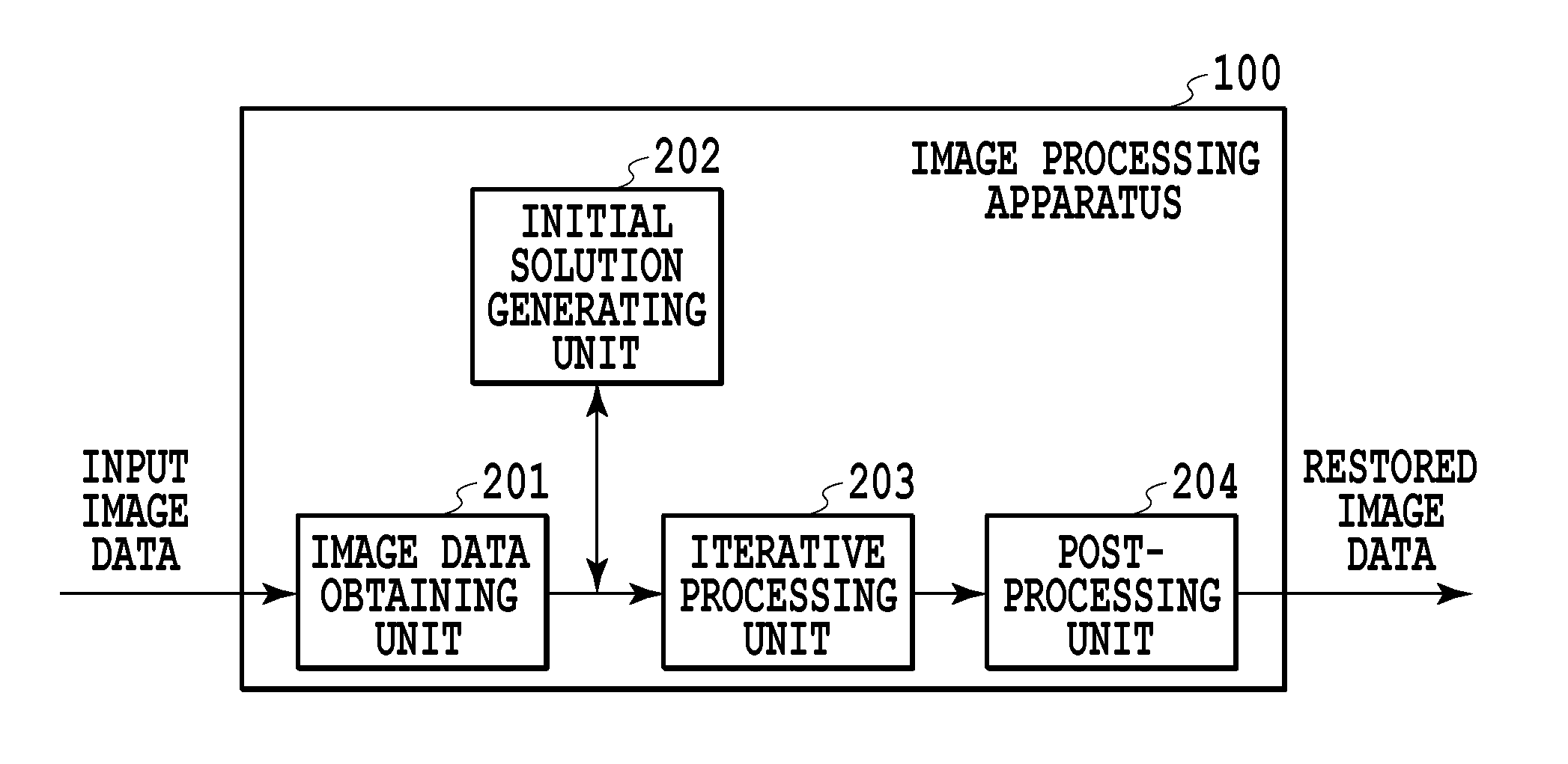
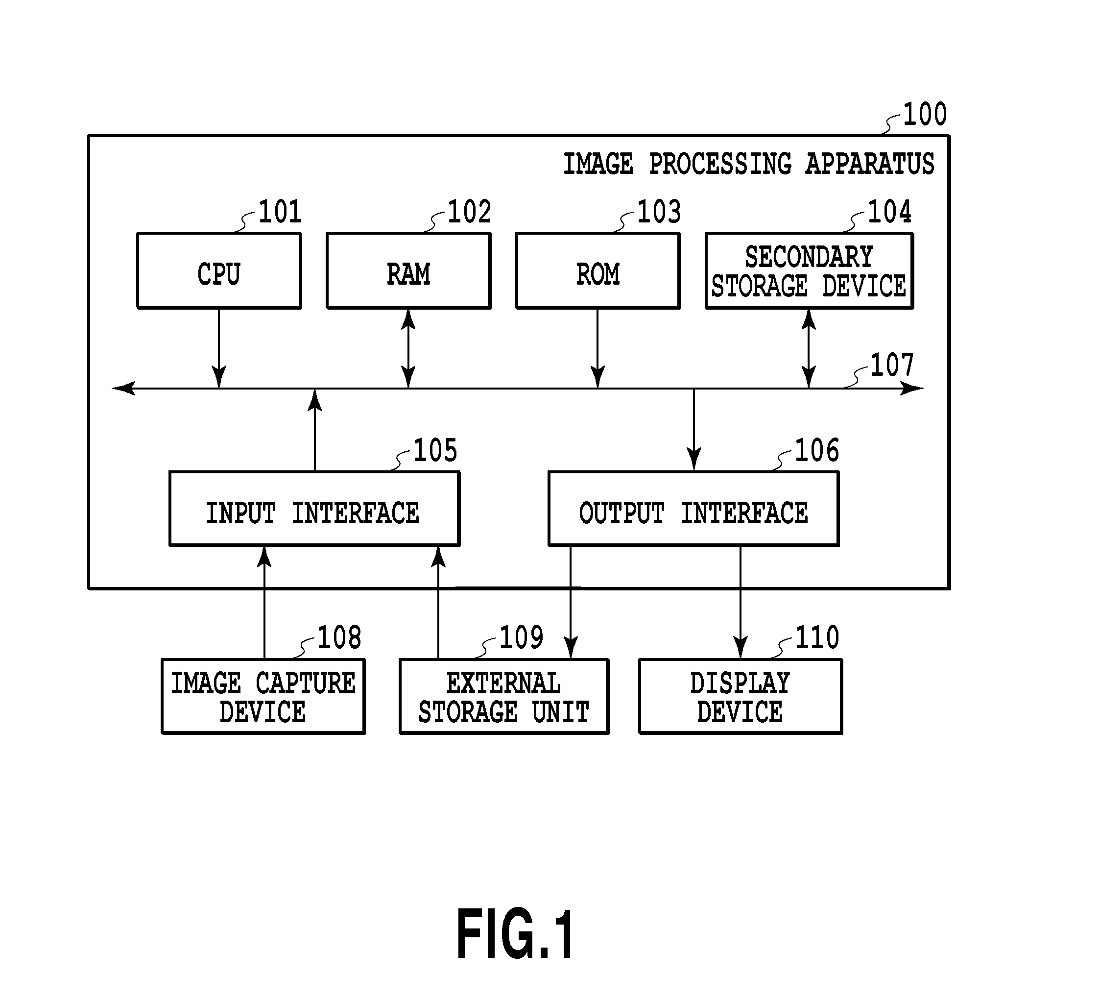
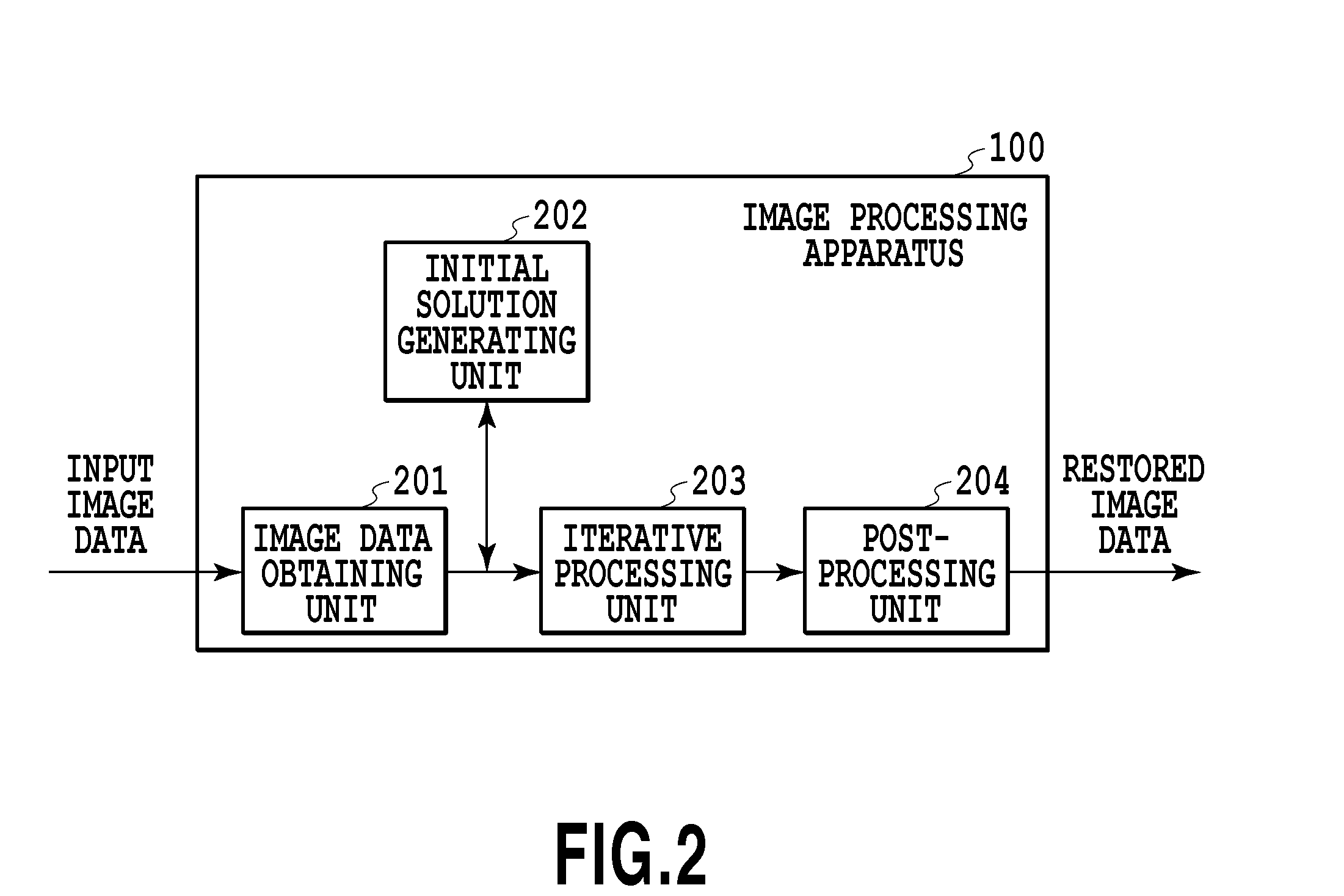
[0021]FIG. 1 is a diagram illustrating an example of a configuration of an image restoration system according to the present invention. The image restoration system is constructed of an image processing apparatus 100, an image capture device 108, an external storage unit 109, and a display device 110.

[0022]The image processing apparatus 100 is constructed of CPU (central processing unit) 101, RAM (random access memory) 102, ROM (read only memory) 103, a secondary storage device 104, an input interface 105, an output interface 106, and a system bus 107. The image capture device 108 and the external storage unit 109 are connected to the input interface 105, and the external storage unit 109 and the display device 110 are connected to the output interface 106.

[0023]The CPU 101 executes a program stored in the ROM 103 with the RAM 102 acting as a working memory, thereby to perform centralized control on units to be described later via the system bus 107. Thereby, various types of proces...

embodiment 2

[0057]In Embodiment 1, description has been given with regard to an example in which an image restoration method of the present invention is applied to a single still image. In Embodiment 2, description will be given with regard to an example in which the image restoration method of the present invention is applied to a time-sequence image group, or equivalently, moving images. Note that description of the same conditions as those of Embodiment 1 will be omitted.

[0058]In Embodiment 2, first, a single frame is extracted from an obtained moving image, and a transmittance distribution is calculated by the method of Embodiment 1. In a case where the image capture device as fixed is used to obtain moving images of a distant scene, the frame-to-frame transmittance distribution can often be considered to be the same. Therefore, use of the aforementioned calculated transmittance distribution for generation of other frames of a restored image eliminates a need to perform the iterative proces...

embodiment 3

[0071]In Embodiment 1, the initial solution of the transmittance distribution is set to the uniform distribution; according to an algorithm of the present invention, processing time or restoration performance, in principle, depends on the initial solution. The reason for this is the same as the reason why convergence or accuracy of a general nonlinear optimization approach depends on the initial solution. In Embodiment 3, therefore, a distribution image obtained by digitizing the degree of focus at each position in an input image is used as the initial solution of the transmittance distribution thereby to achieve a reduction in the processing time. Here, the reason for using the degree of focus to derive the initial solution of the transmittance distribution is that the degree of focus and the transmittance are both quantities which depend on the distance between the subject and the image capture device. In a case of, for example, a relatively distant subject, a value representing t...


PUM


Abstract

An object of the present invention is to provide an image restoration function which ensures physical accuracy, while reducing computational cost, by eliminating a division into local regions. The present invention provides an image processing apparatus including: an initial solution generating unit configured to generate an initial solution of a restored image and an initial solution of a transmittance distribution; and an iterative processing unit configured to receive input data on the generated initial solution of the restored image and input data on the generated initial solution of the transmittance distribution, and to repeat updating of one of the transmittance distribution and the restored image, using the transmittance distribution and the restored image, in such a way as to alternate the updating of the transmittance distribution with the updating of the restored image independently for each pixel.

Description

BACKGROUND OF THE INVENTION[0001]1. Field of the Invention[0002]The present invention relates to image processing for generating an image with the influence of scattered light reduced.[0003]2. Description of the Related Art[0004]Image capturing of an outdoor distant scene for the purpose of monitoring an airport, a harbor area or the like involves a problem of reduction in sharpness of an image caused by light scattered by airborne fine particles (such as fog, rain, snow, dust and smoke). Image capturing for undersea exploration or the like also poses the same problem caused by light scattered by underwater impurities.[0005]An algorithm for performing processing from a single image based on a dark channel is known as a conventional technology related to image restoration processing which is executed in order to compensate for such image quality degradation in an input image (Refer to U.S. Pat. No. 8,340,461). This technology involves resolving an image into local regions, determinin...

Claims


Application Information

Patent Timeline
Patent Type & Authority Applications(United States)
IPC IPC(8): G06T5/00G06K9/46G06K9/52G06V10/60
CPCG06T5/001G06K2009/4666G06K9/46G06K9/52G06V10/60
Inventor HIGAKI, YOSHINARI
Owner CANON KK
Why Eureka
Try Eureka