Power-generating vibration sensor, and tire and electrical device using the same

a technology of vibration sensor and power-generating motor, which is applied in the direction of instruments, specific gravity measurement, braking system, etc., can solve the problems that the power-generating vibration sensor has not achieved sufficient power consumption and size reduction, and achieve the effect of reducing power consumption and siz

Inactive Publication Date: 2015-10-01
PANASONIC INTELLECTUAL PROPERTY MANAGEMENT CO LTD
View PDF10 Cites 11 Cited by
  • Summary
  • Abstract
  • Description
  • Claims
  • Application Information

AI Technical Summary

Benefits of technology

[0015]The present disclosure can provide a power-generating vibration sensor that enables reductions in power consumption and size. Additional benefits and advantages of the disclosed embodiments will become apparent from the specification and drawings. The benefits and / or advantages may be individually obtained by the various embodiments and features of the specification and drawings, which need not all be provided in order to obtain one or more of such benefits and / or advantages.

Problems solved by technology

However, the above-mentioned existing power-generating vibration sensors have not achieved sufficient reductions in power consumption and size.

Method used


Image

  • Power-generating vibration sensor, and tire and electrical device using the same
  • Power-generating vibration sensor, and tire and electrical device using the same
  • Power-generating vibration sensor, and tire and electrical device using the same

Examples


first embodiment

1. First Embodiment

[0034]

[0035]

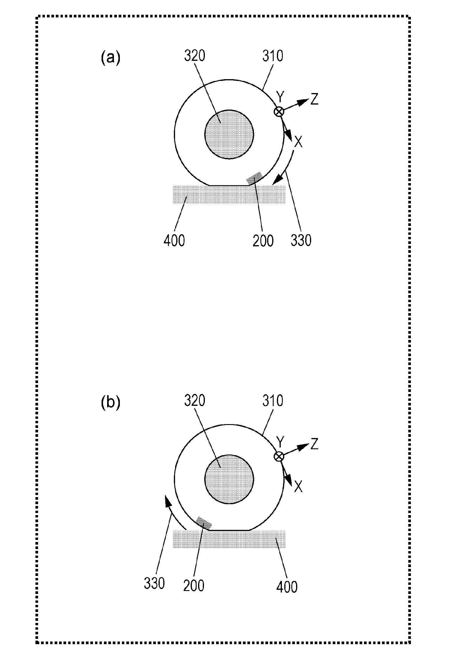
[0036]FIG. 1 includes views illustrating the structure of a tire sensor system according to the first embodiment (an example of a system using the vibration power-generating sensor of the present disclosure). As illustrated in FIG. 1, a transmitter 200 of the first embodiment is mounted inside a tire 310 mounted on a wheel 320. FIG. 1(a) illustrates a state in which the transmitter 200 rotates in a rotation direction 330 of the tire and comes into contact with a road surface 400 through a member of the tire. On the other hand, FIG. 1(b) illustrates a state in which the transmitter 200 rotates in the rotation direction 330 of the tire and moves away from the road surface 400. The transmitter 200 transmits a data signal for determining a tire or road surface condition.

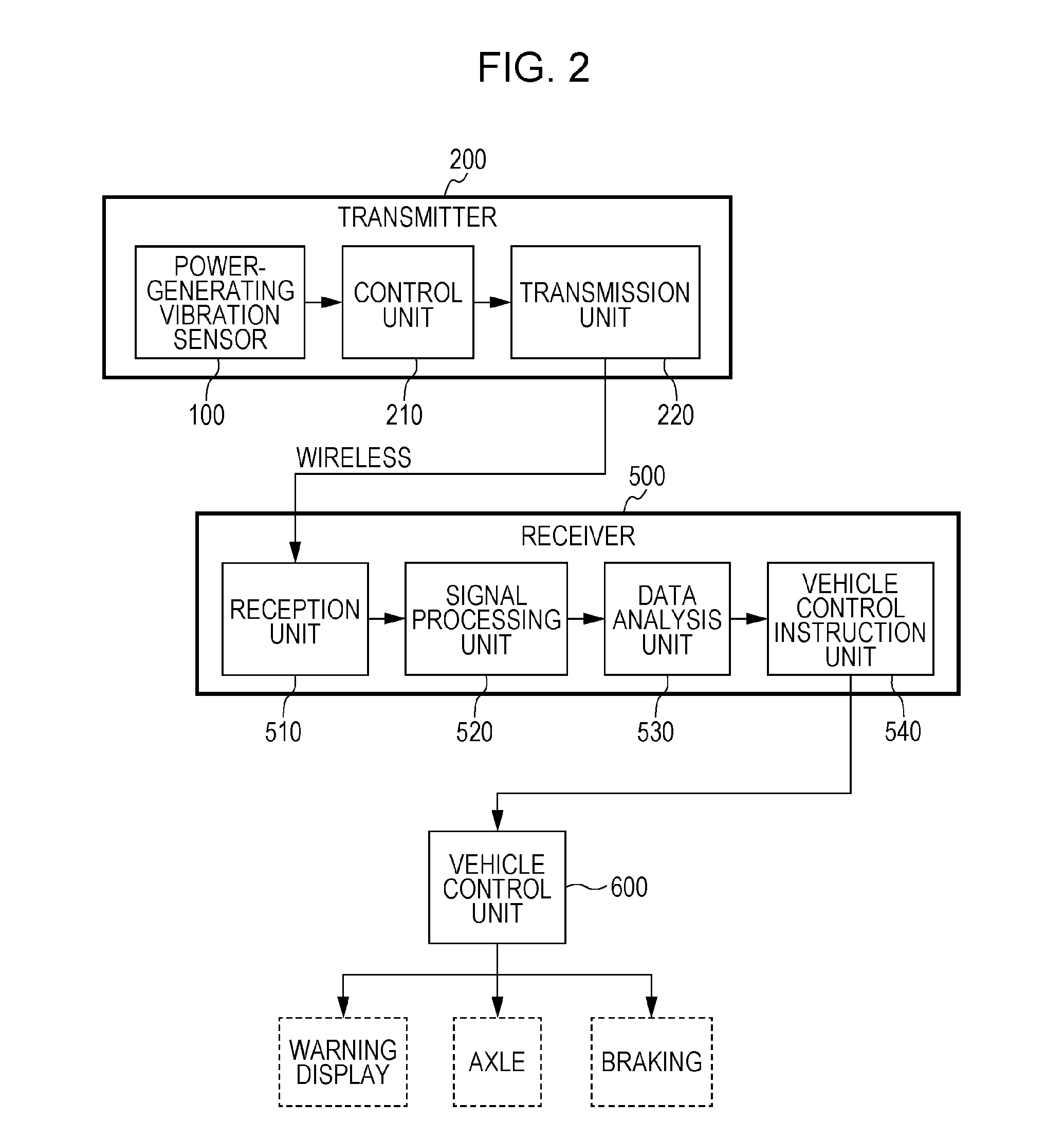
[0037]FIG. 2 is a block diagram illustrating the structure of the tire sensor system according to the first embodiment. The tire sensor system mainly includes the transmitter 200 and a rece...

second embodiment

2. Second Embodiment

[0075]The second embodiment of the present disclosure will be described below.

[0076]

[0077]The second embodiment has the structure illustrated in FIG. 7. A power-generating vibration sensor 1000 of the second embodiment differs from the power-generating vibration sensor 100 of the first embodiment in that the power-generating vibration sensor 100 of the first embodiment generates power using electrets, whereas the power-generating vibration sensor 1000 of the second embodiment generates power using piezoelectric bodies. Except for the above, the structure is the same as that in the first embodiment.

[0078]The structure of the power-generating vibration sensor 1000 will be described with reference to FIG. 7. As described later, the power-generating vibration sensor 1000 includes the movable substrate 110 that vibrates therein.

[0079]The power-generating vibration sensor 1000 includes the lower substrate (first substrate) 111, the upper substrate (second substrate) 10...

third embodiment

[0101]A third embodiment of the present disclosure will be described below.

[0102]In this present embodiment, a method of analyzing vibration data obtained from the power-generating vibration sensors described in the first embodiment and the second embodiment, and a method of estimating a tire or road surface condition using the vibration data will be described.

[0103]

[0104]A method of conversion from a power output waveform into an external vibration waveform will be described with reference to FIG. 10 and FIG. 11. Each of the power-generating vibration sensors (vibration power generators) outputs power corresponding to a waveform of external vibration, and the waveform of external vibration can therefore be obtained by analyzing a power output waveform in the data analysis unit 530 illustrated in FIG. 2.

[0105]In FIG. 10(a), the horizontal axis represents time, and the vertical axis represents a power output based on vibration in a tangential direction X of a round tire. In FIG. 10(b...


PUM


Abstract

A power-generating vibration sensor according to the present disclosure includes a power generation device that converts vibration into power and outputs vibration information, a first power system that extracts the output vibration information, and a second power system that is connected to the power generation device and supplies the power to a transmitter for transmitting the vibration information extracted by the first power system.

Description

BACKGROUND[0001]1. Technical Field[0002]The present disclosure relates to a power-generating vibration sensor, and particularly to a vibration sensor that generates power by an external force and detects vibration, and a tire and an electrical device that use the same.[0003]2. Description of the Related Art[0004]In various electrical devices and the like, physical quantity sensors, such as a pressure sensor, an acceleration sensor, and a strain sensor, are currently used.[0005]In particular, attempts are being made to acquire various pieces of information on the basis of acceleration detected in mobile phones, vehicles, and sensor devices capable of performing such acceleration detection are required. Such a sensor device is provided in a narrow space in an electrical device, and therefore required to be reduced in size and save space. In addition, mobile phones and the like are required to operate for as long as possible on a single charge, a sensor device in vehicles and the like ...

Claims


Application Information

Patent Timeline
Patent Type & Authority Applications(United States)
IPC IPC(8): H02N2/18G01H11/08H02N1/10
CPCH02N2/186G01H11/08H02N1/10G01H11/06B60C23/064B60T8/1725G01H1/003B60T2240/04G01P15/0922G01P2015/0814G01P2015/0828H02N1/08H02N2/188H10N30/306
Inventor NAITO, YASUYUKIONISHI, KEIJI
Owner PANASONIC INTELLECTUAL PROPERTY MANAGEMENT CO LTD
Why Eureka
Try Eureka