Structure and a method for suppressing audio noise of electronic equipment

a technology of electronic equipment and structure, applied in the direction of casings/cabinets/drawers, casings/cabinets/drawers details, electrical equipment, etc., can solve the problems of large reduction in the quality of the final audio signal, distortion, and difficulty in developing the products aforesaid, so as to reduce or repress the noise, increase the heat conduction efficiency and the efficiency of dispersing the accumulated heat

Inactive Publication Date: 2015-10-01
CHEN HUIMIN
View PDF0 Cites 0 Cited by
  • Summary
  • Abstract
  • Description
  • Claims
  • Application Information

AI Technical Summary

Benefits of technology

[0019]1. The audio noise suppressing structure of electronic equipment can be conveniently disposed on an outer periphery or a surface of the electronic equipment for reducing or repressing the noise around the electronic equipment or circuits.
[0020]2. When the electronic equipment is electrified, the audio noise suppressing structure of the electronic equipment or circuits causes shunt circuits resulting from a movement of oxide anions or causes far infrared radiations as well as a resonance effect, thereby increasing the heat conduction efficiency and the efficiency of dispersing the accumulated heat. Accordingly, the thermal accumulation which requires a high power operation can be prevented, and the efficiency of dispersing the heat accumulated in the electronic parts and the circuit of the electronic equipment can be promoted. Thus, the thermal noise resulting from the accumulated heat in the electronic equipment or circuits can be reduced or suppressed in order to increase the quality of the transmitted electronic audio signals.
[0021]3. The audio noise suppressing structure of electronic equipment is conveniently manufactured with a low cost. Therefore, the application of the structure is wider, and the structure is also available to general electronic products.

Problems solved by technology

However, since electronic parts or circuit boards are arranged in high density, techniques for developing the aforesaid products are in fact difficult.
Because the electronic parts or the circuit boards of the electronic equipment are arranged in high density, and the operating signals with a high frequency is developed, these factors render the electronic circuit unable to arrange a complete layout of a distance between parts where noise is generated and other parts.
However, if reflected waves created by the noise suppressing structure are too large, the reflected waves may interfere with the signals of the circuit transmission, and such interference may cause errors.
The aforesaid factors incur audio noise and cause a large decrease in the quality of the final audio signal or a distortion thereof.
As a result, the distortion and the noise are brought about.
Moreover, the influence of the aforesaid external environment and the accumulated heat generated in the internal electronic parts or circuits bring noise with different magnitude and amount to the electronic signals output from an electronic host, and this situation reduces the output quality of the signal.
The aforesaid shortcomings can be solved by using transmission lines or circuits with high conductivity and a better shielding effect, but these specific transmission lines are quite expensive and are unpopular with general products.

Method used


Image

  • Structure and a method for suppressing audio noise of electronic equipment
  • Structure and a method for suppressing audio noise of electronic equipment
  • Structure and a method for suppressing audio noise of electronic equipment

Examples


Embodiment Construction

[0029]The advantages of the present invention over the known prior art will become more apparent upon reading the following descriptions in conjunction with the accompanying drawings.

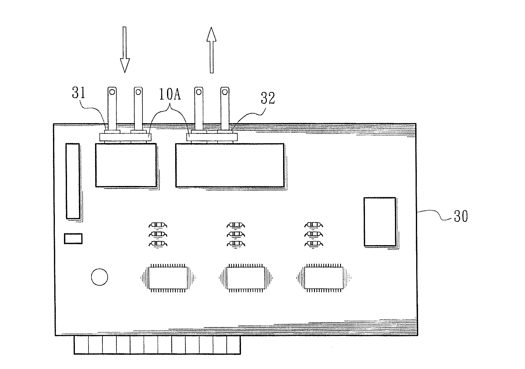
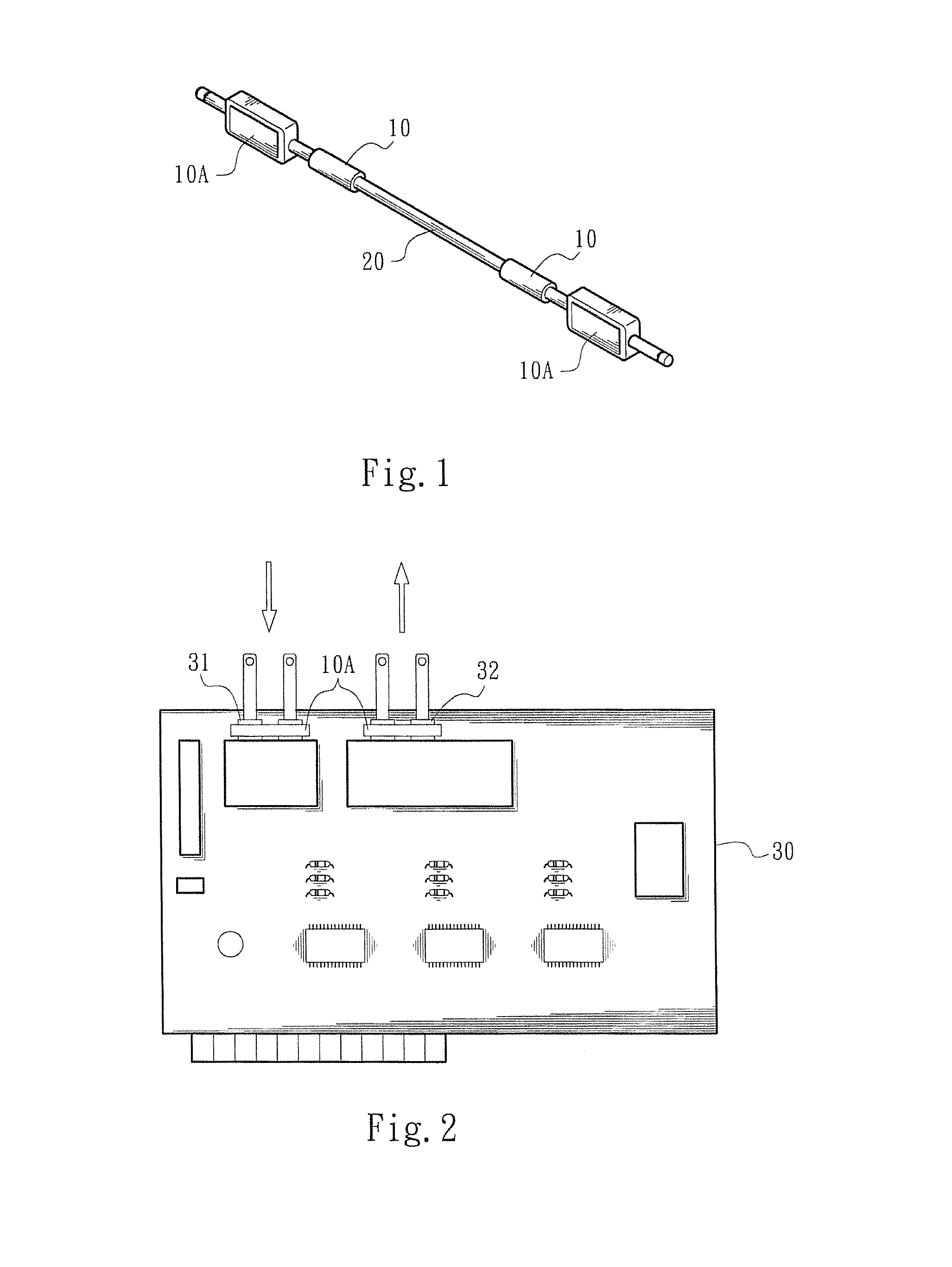
[0030]A method for suppressing audio noise of electronic equipment utilizes an electrically conductive ceramic body to shield an outer periphery of an electronic equipment. Wherein, the electrically conductive ceramic body is formed by combining zirconia with other oxides in a certain proportion and carrying out a sintering process to form an ionized electrically conductive ceramic body whose physical property such as magnetism or frequency, is changed. When an audio noise suppressing structure is disposed on an outer periphery or a surface of a circuit, the suppressing structure can reduce or suppress the audio noise going by the electronic equipment. Moreover, when the circuit of the electronic equipment is electrified, the use of the audio noise suppressing structure further attains a shunt path, gen...


PUM

PropertyMeasurementUnit
temperatureaaaaaaaaaa
operating temperatureaaaaaaaaaa

Abstract

A structure and a method for suppressing audio noise of electronic equipment are carried out by utilizing an audio noise suppressing structure to cover a periphery or a surface of the electronic equipment or circuits thereof. The audio noise suppressing structure mainly comprises zirconia and at least one oxide serving as a stabilizer. The zirconia and the oxide are evenly mixed and sintered with a high temperature to form an electrically conductive ceramic body. In use, because the audio noise suppressing structure is disposed on a periphery or a surface of the electronic equipment or the audio circuits thereof, the electrification of the electronic equipment or audio circuits create shunt conductance, far infrared radiations and a resonance effect to reduce the thermal accumulation. Thus, the accumulated heat possibly caused by working the electronic equipment is reduced or fully dispersed, thereby attaining a decrease in the noise.

Description

CROSS-REFERENCE TO RELATED APPLICATION[0001]This application is a continuation-in-part application of U.S. patent application Ser. No. 13 / 634,049, entitled “A STRUCTURE AND A METHOD FOR SUPPRESSING NOISE OF ELECTRONIC EQUIPMENT”, filed on Sep. 11, 2012, now pending.FIELD OF THE INVENTION[0002]The present invention relates to an audio noise suppressing structure of electronic equipment and a method for suppressing the audio noise with the aid of the structure.DESCRIPTION OF THE RELATED ART[0003]Recently, digital electronic equipment, such as mobile phones, digital cameras and laptops, is developed greatly. Herein, the aforesaid products generally require operating signals having high frequency, small dimension and light weight. However, since electronic parts or circuit boards are arranged in high density, techniques for developing the aforesaid products are in fact difficult.[0004]Because the electronic parts or the circuit boards of the electronic equipment are arranged in high den...

Claims


Application Information

Patent Timeline
Patent Type & Authority Applications(United States)
IPC IPC(8): H05K5/03C04B35/48
CPCC04B35/481H05K5/03H04R2225/49C04B35/486C04B35/6261C04B2235/3206C04B2235/3208C04B2235/3225C04B2235/52C04B2235/5292C04B2235/6562C04B2235/6565C04B2235/6567C04B2235/94
Inventor CHEN, HUIMIN
Owner CHEN HUIMIN
Why Eureka
Try Eureka