Magnetic read head having spin hall effect layer

Inactive Publication Date: 2015-10-08
WESTERN DIGITAL TECH INC
View PDF25 Cites 43 Cited by
  • Summary
  • Abstract
  • Description
  • Claims
  • Application Information

AI Technical Summary

Benefits of technology

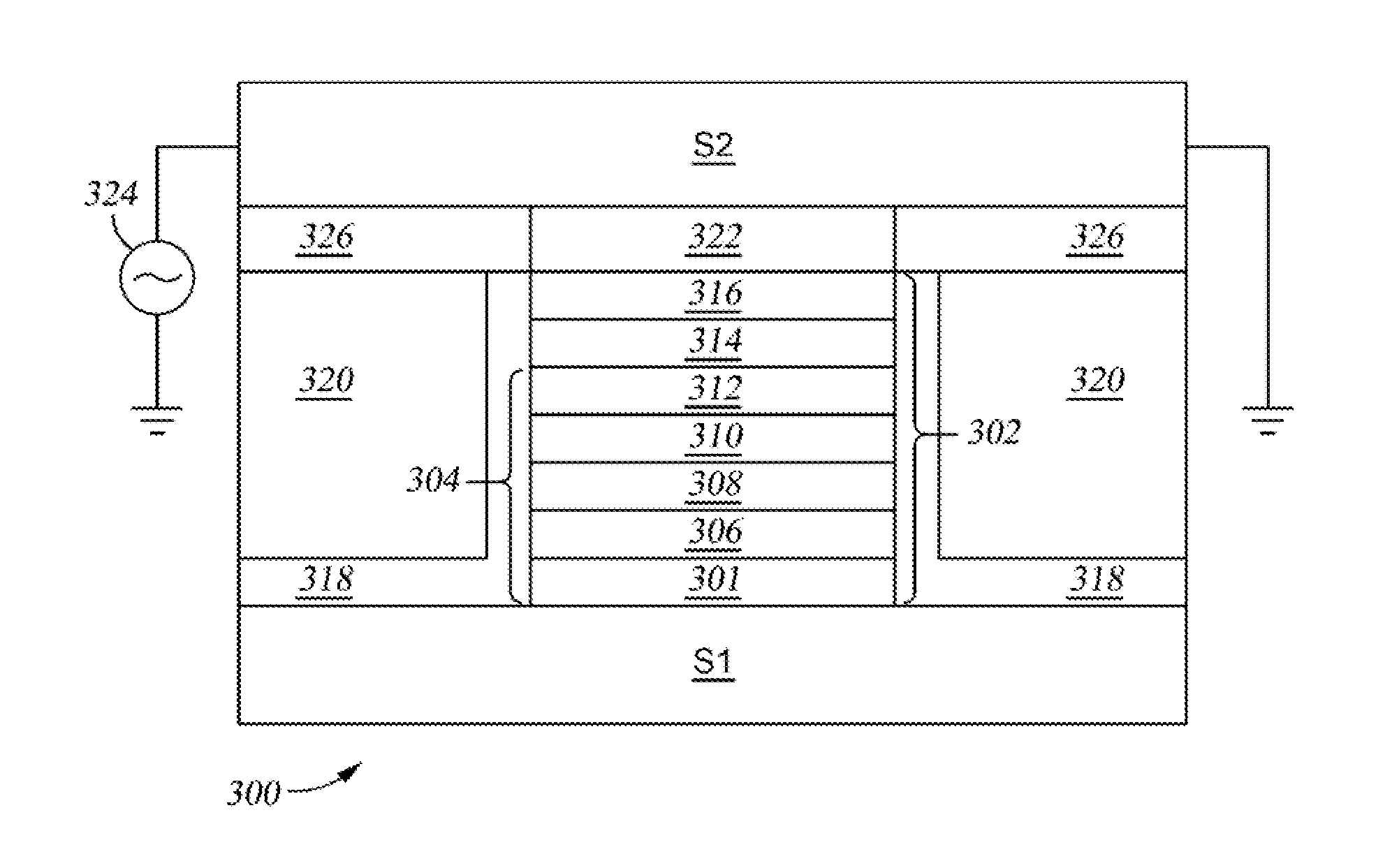
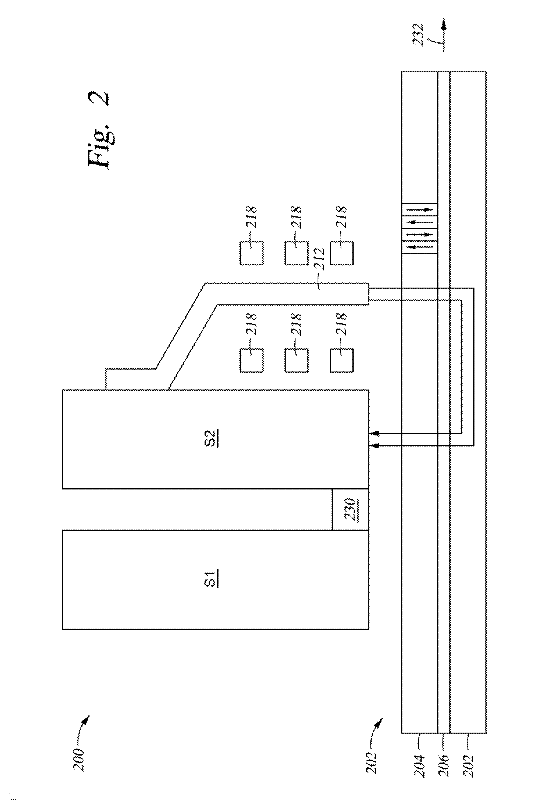
[0008]The embodiments disclosed generally relate to a read head in a magnetic recording head. The read head utilizes a spin Hall effect layer disposed over the free magnetic layer. Electrical bias is applied to the top shield, or lead layer, longitudinally so that the current is longitudinally driven through the spin Hall

Problems solved by technology

The major limiting factor for achieving the required signal to noise ratio (SNR) for magnetoresistive heads, either tunnel magnetoresistive (TMR) heads or current perpendicular to plane-giant magnetoresistive (CPP-GMR) heads, for applications above 1 Tb/in2 is thermal magnetic noise of the free magnetic layer.
The thermal magnetic noise is inversely proportional to the device volume and therefore, the noise becomes a bigger problem as the

Method used


Image

  • Magnetic read head having spin hall effect layer
  • Magnetic read head having spin hall effect layer
  • Magnetic read head having spin hall effect layer

Examples


Example

[0020]To facilitate understanding, identical reference numerals have been used, where possible, to designate identical elements that are common to the figures. It is contemplated that elements disclosed in one embodiment may be beneficially utilized on other embodiments without specific recitation.

DETAILED DESCRIPTION

[0021]In the following, reference is made to embodiments of the invention. However, it should be understood that the invention is not limited to specific described embodiments. Instead, any combination of the following features and elements, whether related to different embodiments or not, is contemplated to implement and practice the invention. Furthermore, although embodiments of the invention may achieve advantages over other possible solutions and / or over the prior art, whether or not a particular advantage is achieved by a given embodiment is not limiting of the invention. Thus, the following aspects, features, embodiments and advantages are merely illustrative and...


PUM


Abstract

The embodiments disclosed generally relate to a read head in a magnetic recording head. The read head utilizes a spin Hall effect layer disposed on the free magnetic layer. Electrical bias is applied to the top shield, or lead layer, longitudinally so that the current is longitudinally driven through the spin Hall effect layer. The spin Hall effect layer may comprise Pt, Ta, W, copper doped with either bismuth or iridium, a noble metal having group 5d non-magnetic impurities, or combinations thereof. The spin Hall effect layer, together with the longitudinally applied bias, reduces the damping in the free magnetic layer and hence, reduces the thermal magnetic noise of the read head.

Description

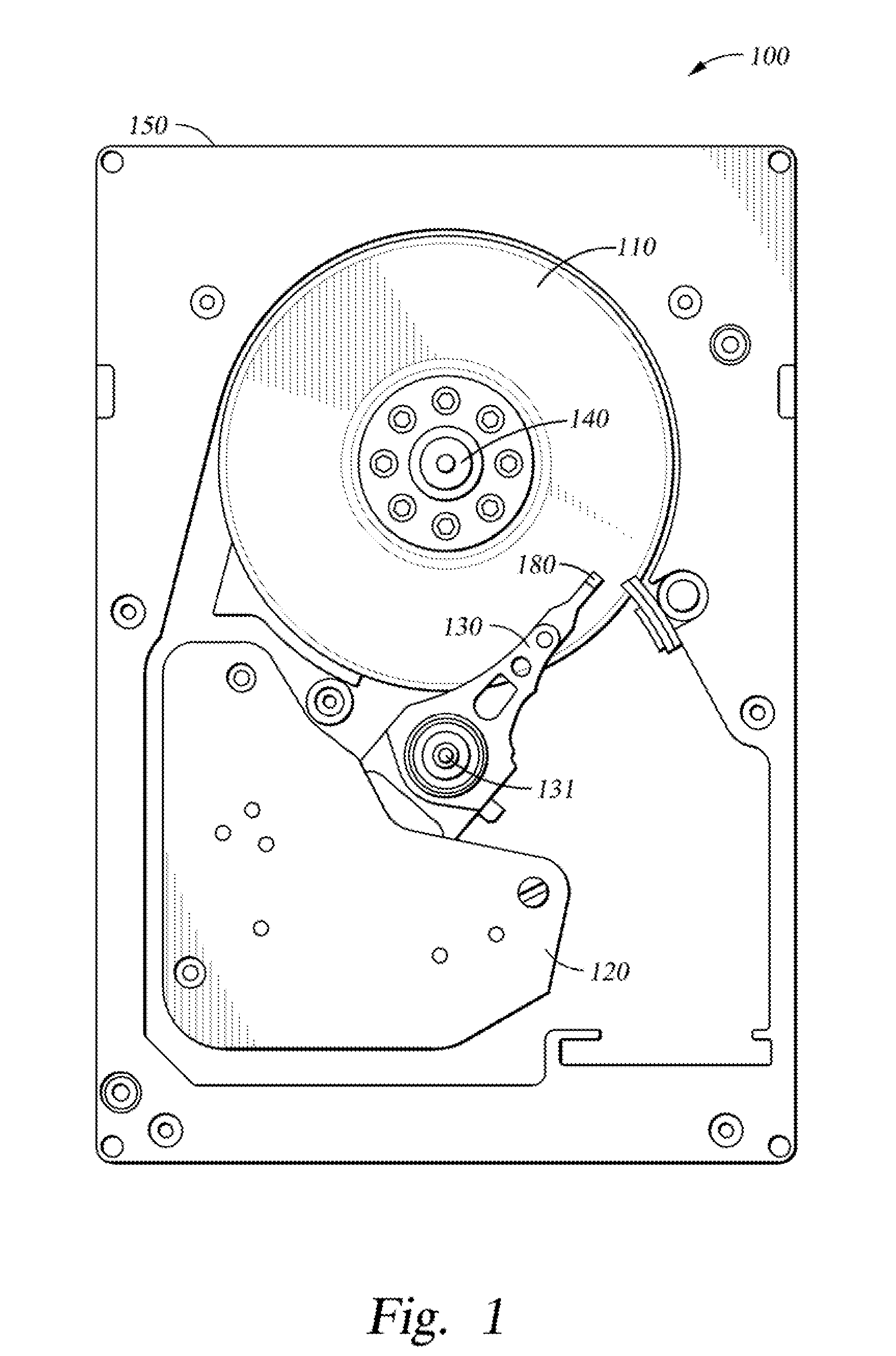
BACKGROUND OF THE INVENTION[0001]1. Field of the Invention[0002]Embodiments disclosed herein generally relate to a magnetic read head for use in a hard disk drive.[0003]2. Description of the Related Art[0004]The heart of a computer is a magnetic disk drive which typically includes a rotating magnetic disk, a slider that has read and write heads, suspension arms above and below the rotating disk and an actuator arm that swings the suspension arm to place the read and / or write heads over selected circular tracks on the rotating disk. The suspension arm biases the slider towards the surface of the disk when the disk is not rotating but, when the disk rotates, air is swirled by the rotating disk adjacent a media facing surface (MFS), such as an air bearing surface (ABS), of the slider causing the slider to ride on an air bearing a slight distance from the surface of the rotating disk. When the slider rides on the air bearing, the write and read heads are employed for writing magnetic tr...

Claims


Application Information

Patent Timeline
IPC IPC(8): G11B5/37G11B5/31
CPCG11B5/37Y10T428/1193Y10T428/11G11B5/3143G11B5/374G11B5/3912G11B5/3929G11B2005/3996G11B5/3932
Inventor MIHAJLOVIC, GORANVAN DER HEIJDEN, PETRUS
Owner WESTERN DIGITAL TECH INC
Why Eureka
Try Eureka