Electric discharge machine with rotary table

a rotary table and electric discharge technology, applied in the direction of metal-working machine components, positioning apparatuses, manufacturing tools, etc., can solve the problems of inevitably large axial dimension of the device, difficult to construct a compact, lightweight rotary table,

Active Publication Date: 2015-10-15
FANUC LTD
View PDF6 Cites 6 Cited by
  • Summary
  • Abstract
  • Description
  • Claims
  • Application Information

AI Technical Summary

Benefits of technology

[0016]According to the present invention, there can be provided a compact, lightweight rotary table device, in which components of a ...

Problems solved by technology

Thus, it is difficult to construct a compact, lightweight rotary table.
According to the technique disclosed in Japanese Patent No. 386295...

Method used


Image

  • Electric discharge machine with rotary table
  • Electric discharge machine with rotary table
  • Electric discharge machine with rotary table

Examples


Embodiment Construction

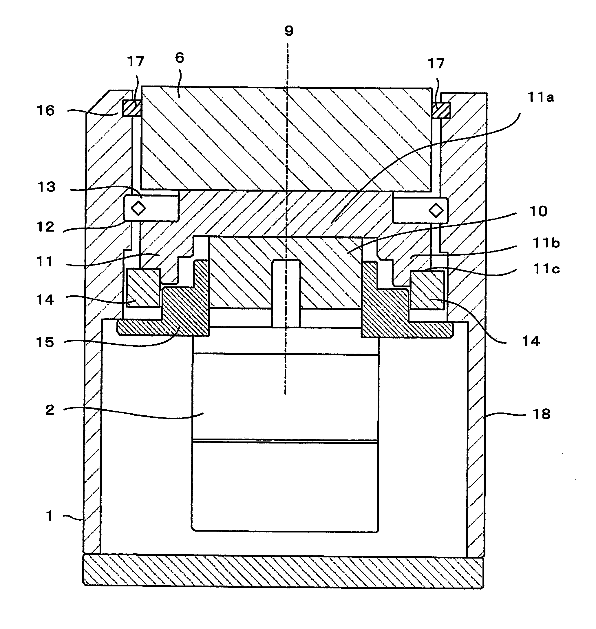
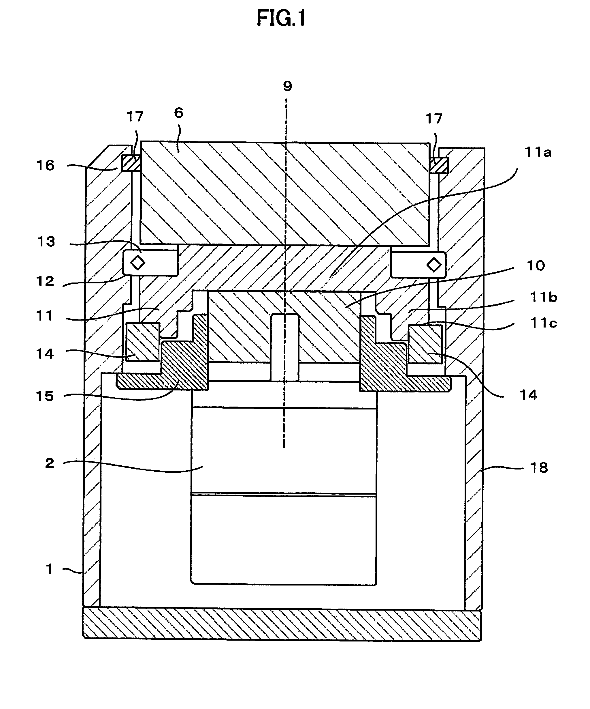
[0022]A first example of a rotary table of an electric discharge machine according to the present invention will first be described with reference to FIG. 1.

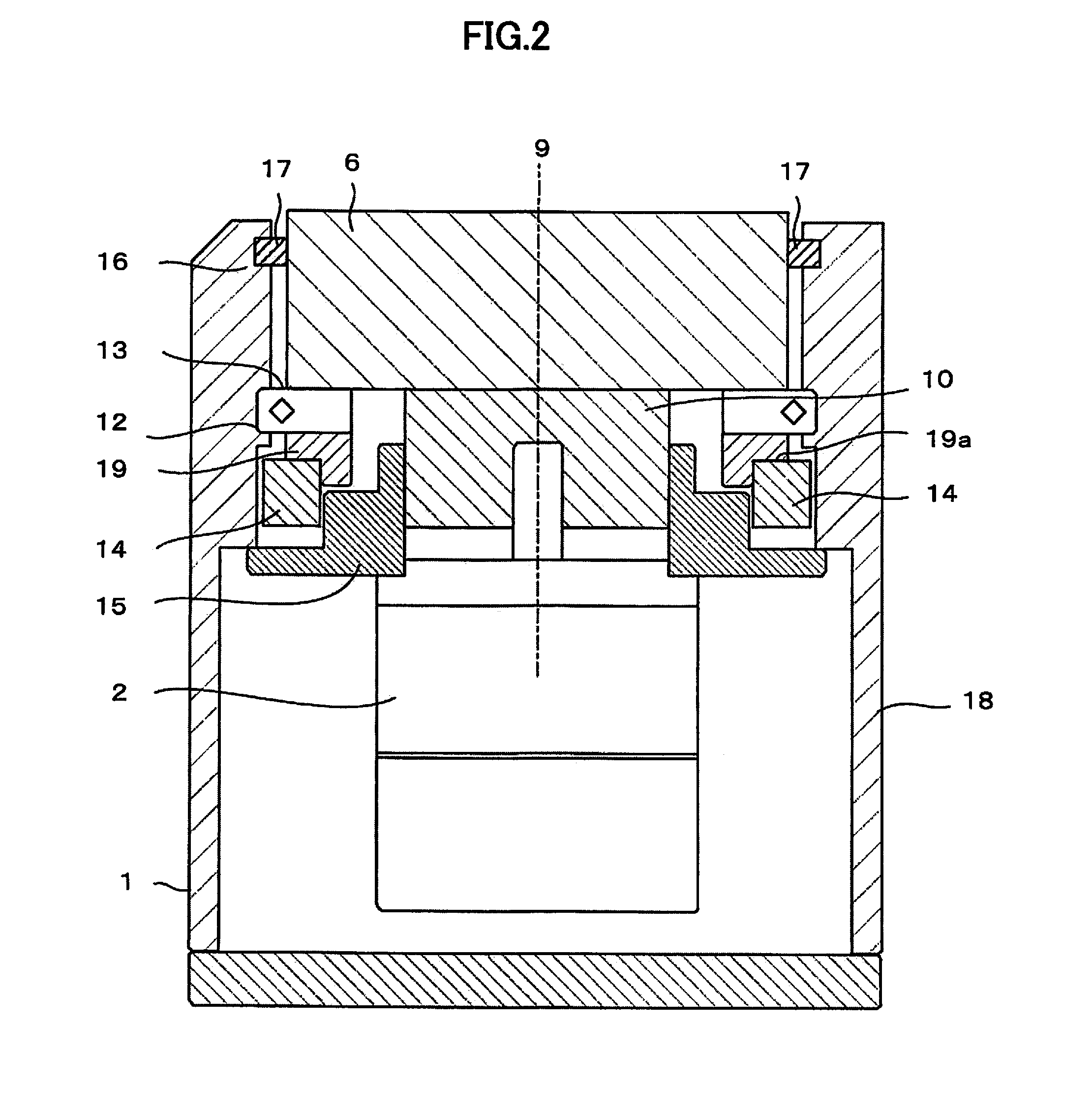
[0023]A housing 18 of a rotary table 1 accommodates a power unit 2, speed reducer 10, fixing member 15, shaft 11, bearing 13, face plate 6, and rotation detector 14.

[0024]The face plate 6 serves to fix a workpiece or a jig to which the workpiece is secured. To prevent a machining fluid or the like from getting into the housing 18, a sealing mechanism 16 formed of a seal member 17 is disposed in a gap between the housing 18 and the face plate 6. The power unit 2 comprises, for example, an electric motor. The fixing member 15 is secured to the housing 18, and the power unit 2 and the speed reducer 10 are attached to the fixing member 15.

[0025]The speed reducer 10 is connected to the power unit 2 and the speed-reduction side of the speed reducer 10 is connected to the shaft 11. Further, the face plate 6 is secured to the shaft 11. ...


PUM


Abstract

A rotary table device of an electric discharge machine is provided with a face plate on which a workpiece is placed, a power unit that generates a driving force for rotating the face plate, and a speed reducer connected to the power unit and configured to reduce the rotational speed of the power unit. The respective centers of rotation of the power unit and the speed reducer are disposed on one and the same axis, and a rotation detector for detecting a rotational position of the face plate is disposed in a space defined by an outer peripheral portion of the speed reducer and an inner wall of a housing of the rotary table device.

Description

BACKGROUND OF THE INVENTION[0001]1. Field of the Invention[0002]The present invention relates to an electric discharge machine with a rotary table.[0003]2. Description of the Related Art[0004]A rotary table used in an electric discharge machine is disposed on a workpiece table in a machining tank that is filled with a machining fluid, and a workpiece as an object of electric discharge machining is fixed on a face plate of the rotary table. Since the machining tank in which the rotary table is placed is limited in size, the rotary table should be as compact as possible. Since the workpiece is sometimes secured directly to the workpiece table in the machining tank, moreover, the rotary table should also be lightweight so that an operator can easily attach and remove it.[0005]An example of the rotary table of an electric discharge machine (see Japanese Patent Application Laid-Open No. 2003-25154) will now be described with reference to FIG. 4.[0006]A power unit 2, first pulley 3, and s...

Claims


Application Information

Patent Timeline
IPC IPC(8): B23H11/00B23H7/26B23H1/00
CPCB23H11/003B23H7/26B23H1/00
Inventor YAMASAKI, MIZUHO
Owner FANUC LTD
Why Eureka
Try Eureka