Vehicle parking control apparatus

a technology for controlling apparatus and vehicles, applied in the direction of braking systems, instruments, analogue processes for specific applications, etc., can solve the problems of difficult establishment of parking wires, and achieve the effect of prolonging the service life of the parking mechanism

Active Publication Date: 2015-10-15
HONDA MOTOR CO LTD
View PDF6 Cites 10 Cited by
  • Summary
  • Abstract
  • Description
  • Claims
  • Application Information

AI Technical Summary

Benefits of technology

[0014]In claim 1, it is configured to have an apparatus for controlling parking of a vehicle having a shift-by-wire type parking mechanism, a foot brake, an automatic braking system, a stop detection means, a road surface gradient detection means and a vehicle travel speed detection means, wherein at a time of causing a parking mechanism to execute parking process to switch the parking gear to the locked state when a predetermined parking condition is established and a detected road surface gradient is equal to or greater than a predetermined value, it is determined whether the foot brake has been operated, a travel speed control is executed for controlling operation of the automatic braking system to make the travel speed of the vehicle greater than zero but equal to or less than the set speed, if it is determined that the foot brake has not been operated, and the parking process is then executed, so that when the vehicle is parked on a road surface whose gradient is equal to or greater than the predetermined value, establishment of the locked state of the parking mechanism is facilitated during the parking process and the driver can be prompted to operate the foot brake (brake pedal) and the parking brake.
[0015]To explain further, by defining the set speed as, for example, a very low speed at which the parking gear and the parking pole can engage, it becomes possible to engage the parking pole with the parking gear even if the vehicle should creep during parking on a road surface of a gradient equal to or greater than the predetermined value, thereby making it easy to establish the locked state of the parking mechanism during the parking process.
[0016]Moreover, when the foot brake is determined not to have been operated by the driver, travel speed control is executed to control the operation of the automatic braking system to make the travel speed of the vehicle greater than zero but equal to or less than the set speed, in other words so as not to stop the vehicle. As a result, a driver who intends to leave the vehicle can be prompted to operate the parking brake, while operating the foot brake.
[0017]In addition, it is possible to extend the service life of the parking mechanism and, since the driver conducts the braking operation by himself / herself, to save the driver from feeling a jolt owing to sudden locking.
[0018]In claim 2, it is configured such that, the predetermined parking condition includes that an opening of a door of the vehicle has been detected, so that situations in which the driver is prompted to perform a brake operation can again be limited to the minimum necessary range.
[0019]In claim 3, it is configured such that, the predetermined parking condition includes that the driver is on board the vehicle, so that situations in which the driver is prompted to perform a brake operation can similarly be limited to the minimum necessary range.

Problems solved by technology

So when the gradient of the road surface the vehicle sits on is equal to or greater than a certain angle, the vehicle is liable to creep or roll down during parking and thus make it difficult for the parking wire to establish the locked state by pulling the parking pole.

Method used


Image

  • Vehicle parking control apparatus
  • Vehicle parking control apparatus
  • Vehicle parking control apparatus

Examples


embodiment 1

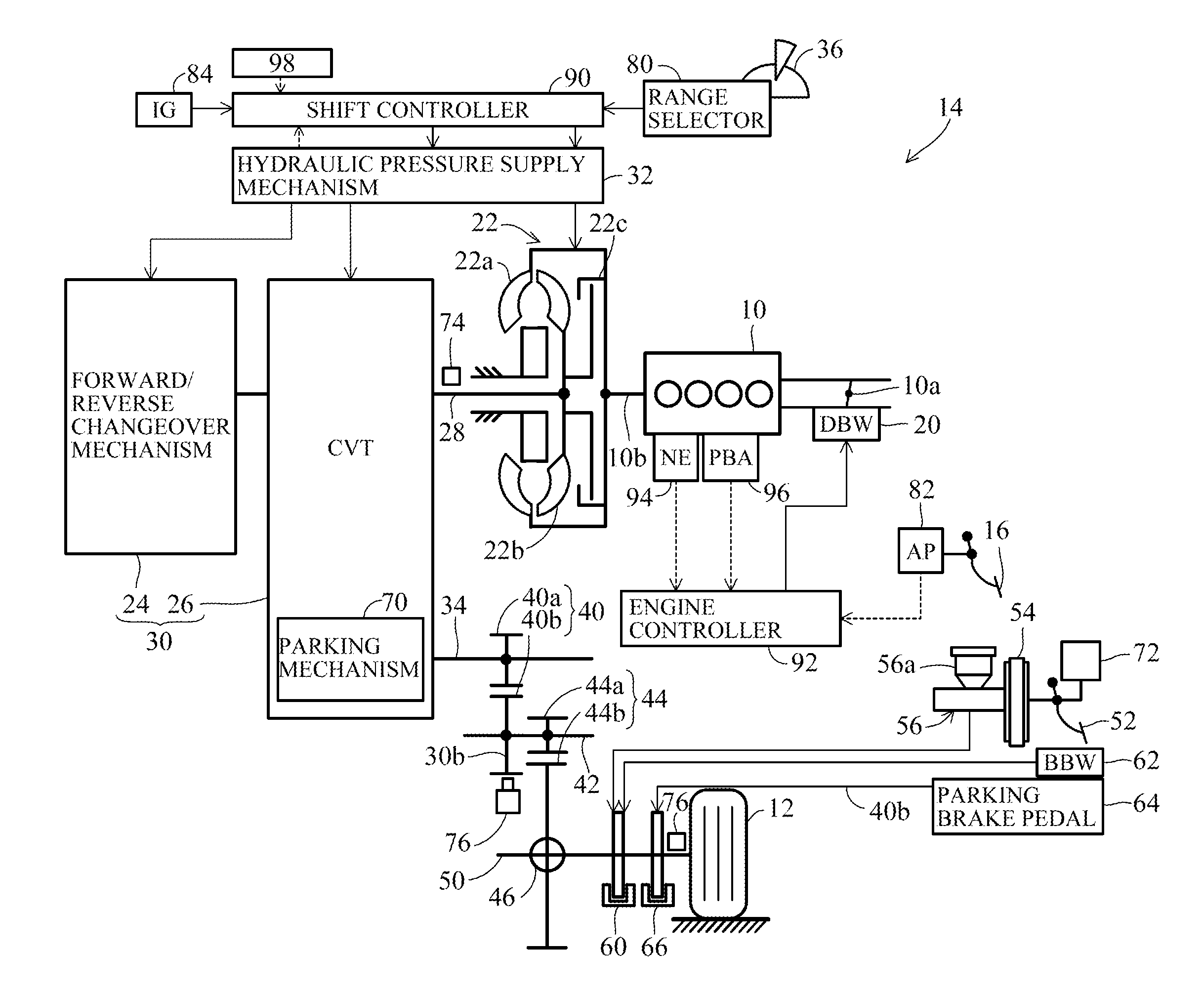
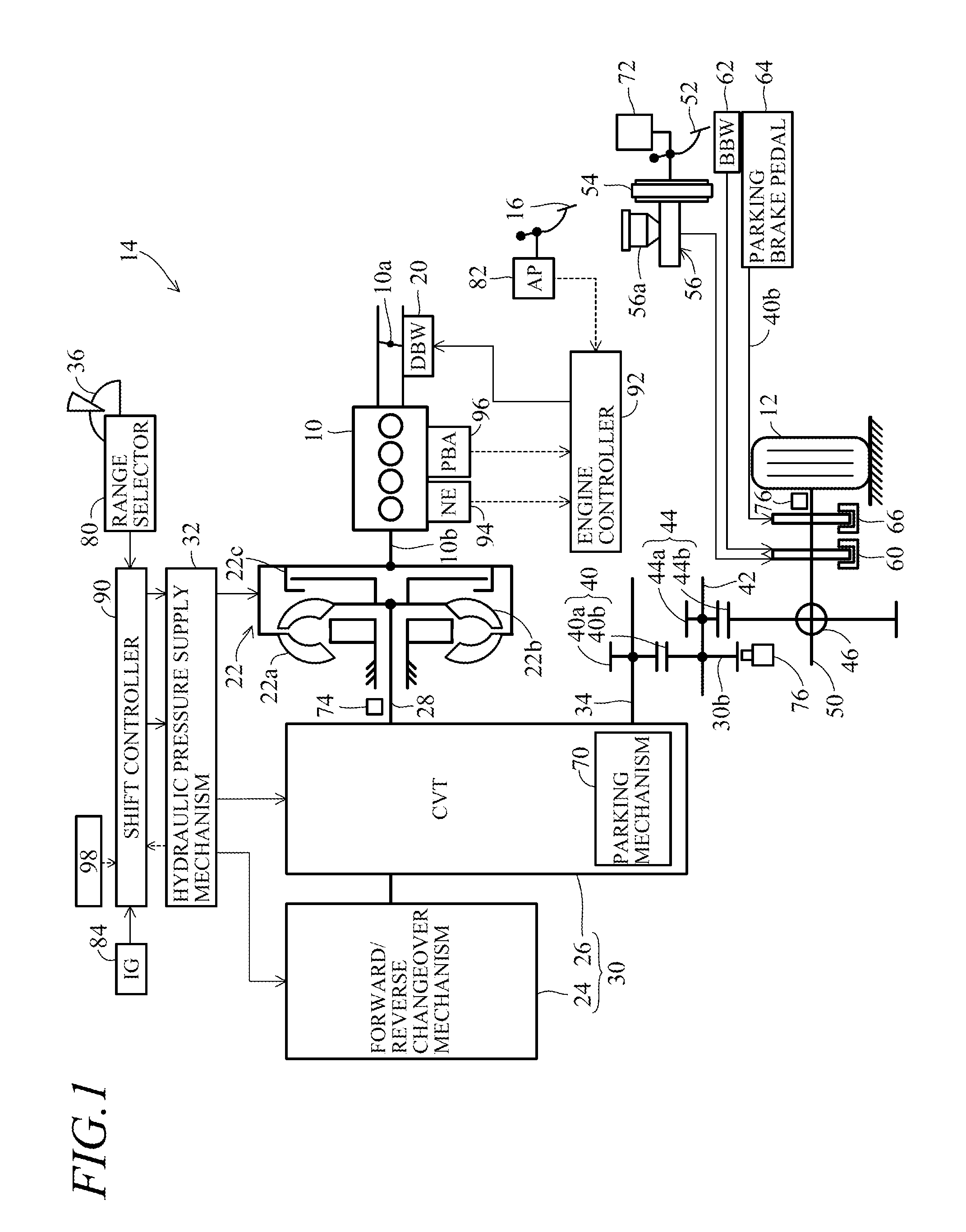
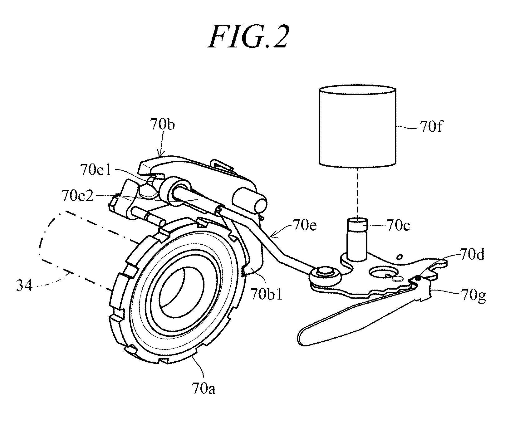
[0029]FIG. 1 is an overall schematic view of a vehicle parking control apparatus according to a first embodiment of this invention, and FIG. 2 is an explanatory view showing a realistic representation of the parking mechanism shown in FIG. 1.

[0030]Reference numeral 10 in FIG. 1 designates an engine (power source). The engine 10 is a four-cylinder, gasoline-fueled, internal combustion engine that is installed in a vehicle 14 equipped with driven wheels (vehicle wheels) 12 (the vehicle 14 is depicted partially by representative components including the engine 10 and driven wheels 12).

[0031]A throttle valve 10a installed in an air-intake system of the engine 10 is mechanically disconnected from an accelerator pedal 16 installed on the floor at a vehicle operator's seat and is connected to and opened / closed by a DBW (Drive By Wire) mechanism 20 comprising an electric motor or other actuator.

[0032]Intake air metered by the throttle valve 10a flows through an intake manifold (not shown) t...

embodiment 2

[0083]FIG. 5 is a flowchart showing the operation of a vehicle parking control apparatus according to a second embodiment of this invention, specifically, the operation of the shift controller 90. FIG. 6 is a timing chart of the processing of FIG. 5.

[0084]Now to explain, the program begins at S100, in which it is determined whether the gradient (slope) of the road surface at the current location of the vehicle 14 detected by the slope sensor 98 is equal to or greater than the predetermined value. When the result in S100 is negative, i.e., when the road surface where the vehicle 14 is currently located is found to be flat or gently sloped, the program proceeds to S102, in which it is determined whether the vehicle speed detected from the wheel speed sensors 76 is equal to or less than the aforesaid speed at which the vehicle 14 can be stopped.

[0085]When the result in S102 is negative, parking control is not required, so the ensuing processing steps are skipped, and when it is affirma...


PUM


Abstract

At a time of causing a parking mechanism to execute parking process to switch a parking gear to a locked state when a predetermined parking condition is established and a detected road surface gradient is equal to or greater than a predetermined value, it is determined whether a foot brake has been operated, operation of an automatic braking system is controlled to make a travel speed of the vehicle greater than zero but equal to or less than a set speed if it is determined that the foot brake has not been operated, and the parking process is then executed.

Description

TECHNICAL FIELD[0001]This invention relates to a vehicle parking control apparatus, more specifically to a shift-by-wire type vehicle parking control apparatus.BACKGROUND ART[0002]A direct-type parking mechanism uses a wire connected to a shift lever to enable switching of a parking gear fastened to an output shaft of an automatic transmission between a rotatable unlocked state and an non-rotatable locked state. As an alternative, a shift-by-wire type parking mechanism has recently been developed that does away with the wire-to-gear mechanical connection by using an actuator connected to the parking gear to operate the gear.[0003]During the process of parking, the shift-by-wire type parking mechanism needs more time than the direct type to switch from the unlocked state to the locked state. So when the gradient of the road surface the vehicle sits on is equal to or greater than a certain angle, the vehicle is liable to creep or roll down during parking and thus make it difficult for...

Claims


Application Information

Patent Timeline
Patent Type & Authority Applications(United States)
IPC IPC(8): B60T7/12B60T8/32B60T8/24
CPCB60T7/12B60T8/32B60T8/24B60T1/005B60T1/065B60T7/042B60T2240/06F16D63/006F16H63/486F16H2059/663
Inventor KAMO, SHUNJI
Owner HONDA MOTOR CO LTD
Why Eureka
Try Eureka