Apparatus and a method for treatment of mined material with electromagnetic radiation

a technology of electromagnetic radiation and apparatus, which is applied in the direction of electrical apparatus, grain treatment, electric/magnetic/electromagnetic heating, etc., can solve the problems of micro-cracks and macro-cracks, and achieve the effect of reducing power consumption and propagating electromagnetic radiation from the radiation inlet region into the further passag

Active Publication Date: 2015-10-15
TECHNOLOGICAL RESOURCES
View PDF9 Cites 0 Cited by
  • Summary
  • Abstract
  • Description
  • Claims
  • Application Information

AI Technical Summary

Benefits of technology

[0054]In one embodiment the apparatus also comprises a further passage for guiding the fragments of the mined material away from the radiation inlet region. In this embodiment the apparatus may have a further reflective structure that is below and typically subjacent the radiation inlet region and may be of the above-described type. The further reflective structure may be arranged such that propagation of the electromagnetic radiation from the radiation inlet region into the further passage is reduced, which has the advantage that power consumption may be reduced. The further reflective structure may be arranged such that an electric field intensity associated with the electromagnetic radiation decreases at a rate of at least 15, 20, 25, 30, 35, 40, 45 or 50 dB / m in a direction from the radiation inlet region into the further passage. Further, the further reflective structure may be arranged such that a power density associated with the electromagnetic radiation within the heated microwave absorbent phase of the fragments decreases at a rate of at least 30, 40, 50, 60, 70, 80, 90 or 100 dB / m in a direction form the cavity into the further passage.

Problems solved by technology

The fragments may include gangue and valuable material (such as copper or iron containing minerals) and the exposure of the fragments to high power-density electric fields related to the high intensity microwave radiation causes preferential heating and resultant thermal expansion of some of the components of the fragments, which results in formation of micro-cracks and macro-cracks.

Method used


Image

  • Apparatus and a method for treatment of mined material with electromagnetic radiation
  • Apparatus and a method for treatment of mined material with electromagnetic radiation
  • Apparatus and a method for treatment of mined material with electromagnetic radiation

Examples


Embodiment Construction

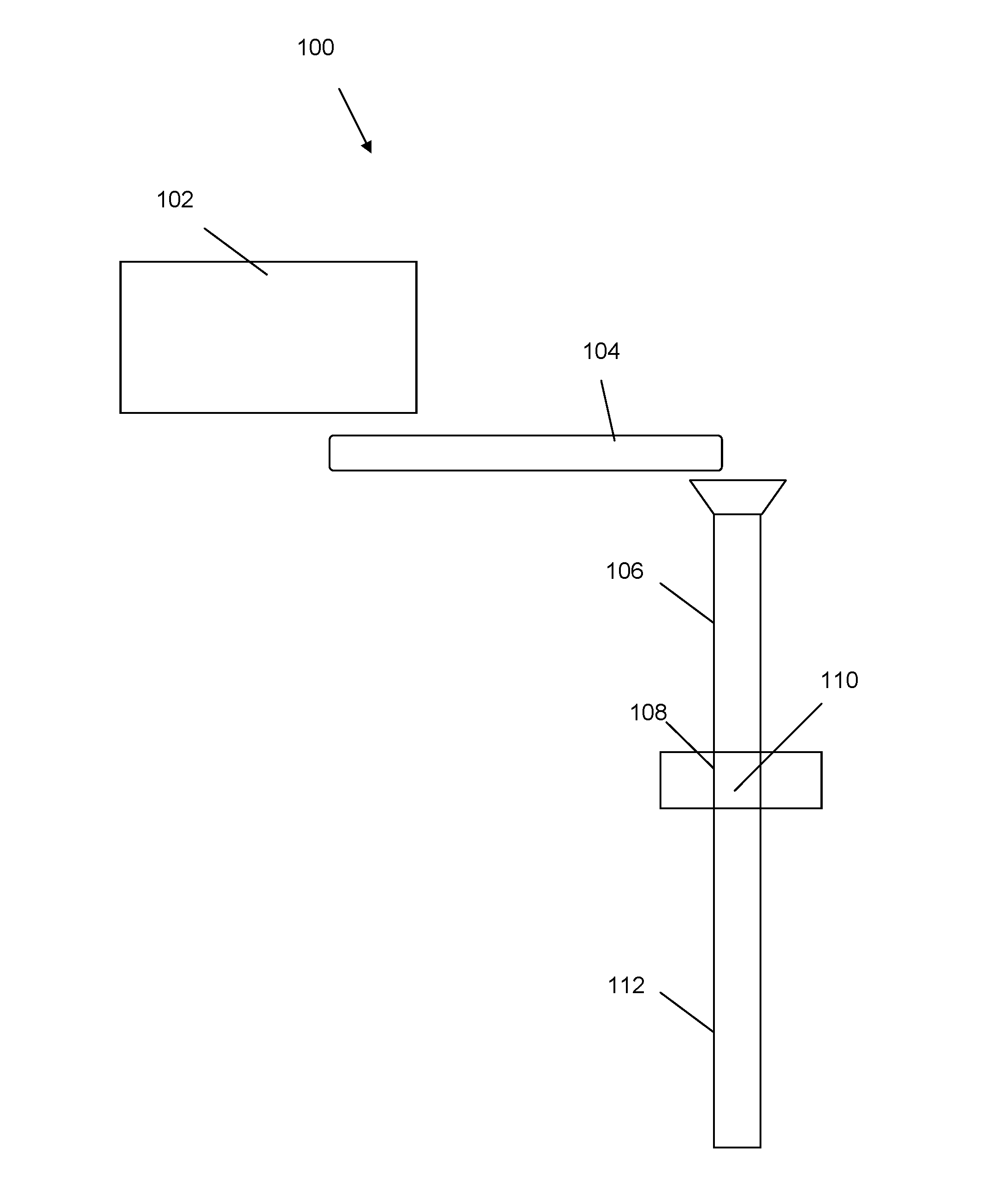
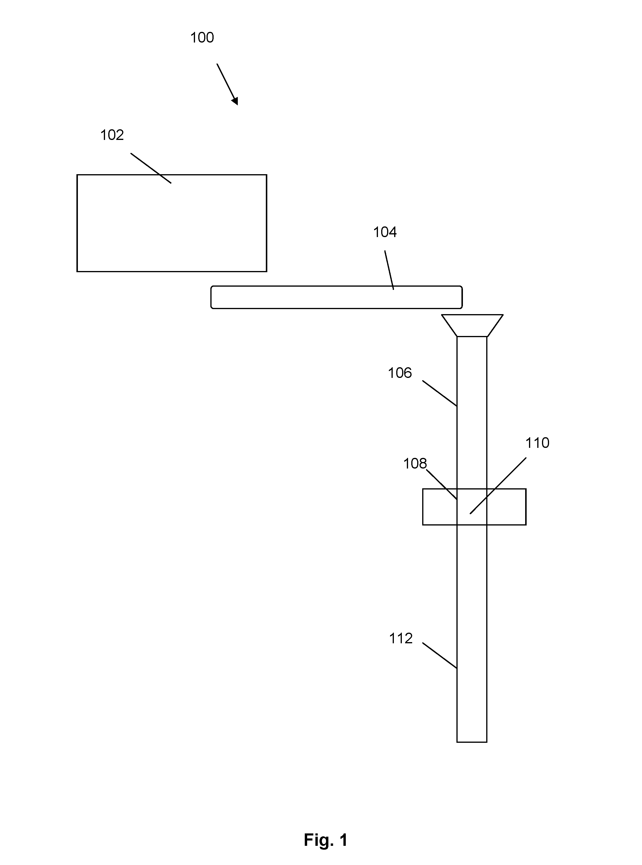
[0081]Referring initially to FIG. 1, an apparatus for treatment of mined material in accordance with a specific embodiment of the present invention is now described. The apparatus 100 comprises a crusher 102 that is arranged to receive mined material. The mined material may comprise an ore, such as a copper, nickel or iron containing ore or another suitable ore. The crusher 102 is in this embodiment arranged to crush the mined material such that fragments of the mined material have a P80 size of the order of 10 to 75 mm.

[0082]The fragments of the mined material are then directed by conveyor belt 104 into a chute that comprises chute portions 106, 108 and 112. The chute provides a vertical passage through which the fragments of the mined material fall by gravity in the form of a packed bed. The chute portion 106 is a conduit that surrounds the falling fragments of the mined material and the chute portion 108 guides the fragments of the mined material through a microwave inlet region ...


PUM

PropertyMeasurementUnit
lengthaaaaaaaaaa
lengthaaaaaaaaaa
sizeaaaaaaaaaa

Abstract

The present disclosure provides an apparatus for treatment of mined material. The apparatus comprises a source for generating electromagnetic radiation and a microwave inlet region for exposing fragments of the mined material to the electromagnetic radiation. Further, the apparatus comprises a reflective structure adjacent the microwave inlet region and providing, or surrounding, a passage for guiding the fragments of the mined material to the microwave inlet region. The reflective structure is arranged to attenuate penetration of the electromagnetic radiation from the microwave inlet region into the passage during throughput of the fragments of the mined material.

Description

FIELD OF THE INVENTION[0001]The present invention relates to an apparatus and a method for treatment of mined material with electromagnetic radiation, and relates particularly, although not exclusively, to an apparatus and a method for treatment of mined materials with microwave radiation.[0002]The term “mined” material is understood herein to include metalliferous material and non-metalliferous material. Iron-containing and copper-containing ores are examples of metalliferous material. Coal is an example of a non-metalliferous material. The term “mined” material is also understood herein to include (a) run-of-mine material and (b) run-of-mine material that has been subjected to at least primary crushing or similar size reduction after the material has been mined and prior to being sorted. Further, the term “mined” material includes mined material that is in stockpiles.[0003]The present invention also relates to recovering valuable material from mined material and relates particular...

Claims


Application Information

Patent Timeline
Patent Type & Authority Applications(United States)
IPC IPC(8): C22B1/24B02C19/18H05B6/80H05B6/78C22B4/00C22B4/08
CPCC22B1/24C22B4/00B02C19/18H05B6/80H05B6/78C22B4/08C22B1/00
Inventor DIMITRAKIS, GEORGIOSKINGMAN, SAMUELDODDS, CHRISTOPHERBATCHELOR, ANDREWJONES, ALED
Owner TECHNOLOGICAL RESOURCES
Why Eureka
Try Eureka