Method to determine a direction and amplitude of a current velocity estimate of a moving device

a technology of current velocity and estimation method, applied in the direction of distance measurement, navigation instruments, instruments, etc., can solve the problems of monocular vision-only solutions suffering from the so-called scale ambiguity, and the scale of the velocity remains unknown

Inactive Publication Date: 2015-10-15
ECOLE POLYTECHNIQUE FEDERALE DE LAUSANNE (EPFL)
View PDF2 Cites 22 Cited by
  • Summary
  • Abstract
  • Description
  • Claims
  • Application Information

AI Technical Summary

Benefits of technology

[0021]A key innovative step is the introduction of the optic-flow direction constraint. This constraint is used to correct for inertial sensor drift along the axes perpendicular to the direction of motio

Problems solved by technology

The estimation of the rotation speed is a solved problem nowadays thanks to the broadly available rate-gyroscopes, and the challenge really lies in the linear velocity estimation.
This procedure is prone to the correspondence problem arising when features cannot be matched from frame to frame.
Optic-flow sensors thus exist in very small and cheap packages.
All monocular vision-only solutions suffer from the so-called scale ambiguity when trying to estimate motion or structure as there is no way for any vision sensor to distinguish fast motion in a big environment to slow motion in a tiny environment.
Such optic-flow-based methods can estimate the angular speed together with the direction of motion, however, the scale of the velocity remains unknown for the reasons described above (scale ambiguity).
Such a method has the drawback that it will only work below the limited range of the distance sensor and for relatively flat surfaces to ensure that the tracked features are all at the approximate distance given by the ultrasonic sensor.
In case of monocular visual SFM, the resulting estimation suffers from a scale ambiguity.
The algorithms require a relatively high computing power and memory, resulting in fairly bulky setups (when these algorithms aren't run offline on a computer or in simulation).
These algorithms rely on feature tracking, but don't rely on the e

Method used


Image

  • Method to determine a direction and amplitude of a current velocity estimate of a moving device
  • Method to determine a direction and amplitude of a current velocity estimate of a moving device
  • Method to determine a direction and amplitude of a current velocity estimate of a moving device

Examples


Embodiment Construction

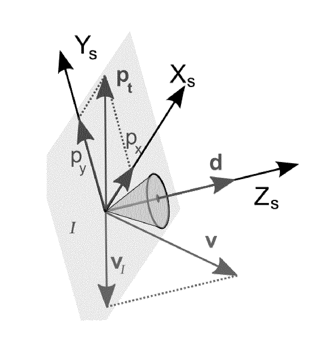
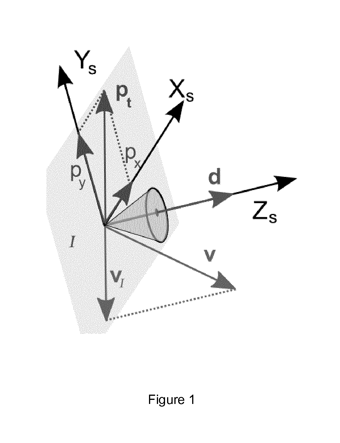
[0034]The invention consists in a new method for the estimation of ego-motion (the direction and amplitude of the velocity) of a mobile device comprising optic-flow and inertial sensors (hereinafter the apparatus). The velocity is expressed in the apparatus's reference frame, which is moving with the apparatus. This section introduces the optic-flow direction constraint and describes a method that relies on short-term inertial navigation and the direction of the translational optic-flow in order to estimate ego-motion, defined as the velocity estimate (that describes the speed amplitude and the direction of motion).

[0035]A key characteristic of the invention is the use of optic-flow without the need for any kind of feature tracking. Moreover, the algorithm uses the direction of the optic-flow and does not need the amplitude of the optic-flow vector, thanks to the fact that the scale of the velocity is solved by the use of inertial navigation and changes in direction of the apparatus...


PUM


Abstract

A new method for the estimation of ego-motion (the direction and amplitude of the velocity) of a mobile device comprising optic-flow and inertial sensors (hereinafter the apparatus). The velocity is expressed in the apparatus's reference frame, which is moving with the apparatus. The method relies on short-term inertial navigation and the direction of the translational optic-flow in order to estimate ego-motion, defined as the velocity estimate (that describes the speed amplitude and the direction of motion). A key characteristic of the invention is the use of optic-flow without the need for any kind of feature tracking. Moreover, the algorithm uses the direction of the optic-flow and does not need the amplitude, thanks to the fact that the scale of the velocity is solved by the use of inertial navigation and changes in direction of the apparatus.

Description

1 INTRODUCTION[0001]The present invention concerns a method to determine the ego-motion of a mobile device, or in other words, the estimation of the direction and amplitude of the velocity of the mobile device using embedded sensors, in particular inertial and optic-flow sensors.[0002]By definition, the ego-motion not only comprises the speed and amplitude of the motion but also includes rotational speed. The estimation of the rotation speed is a solved problem nowadays thanks to the broadly available rate-gyroscopes, and the challenge really lies in the linear velocity estimation.2 BACKGROUND[0003]The topic of ego-motion estimation being widely researched, a lot of different solutions can be found in the literature. Vision, completed with other sensors or not, is a sensor modality that can be found in a large number of these solutions. Solutions not relying on vision are usually targeted at specific problems (such as airspeed sensors for unique direction of motion, or odometry for ...

Claims


Application Information

Patent Timeline
IPC IPC(8): G01P3/36
CPCG01P3/36G01C22/00G01C21/1656G05D1/00
Inventor BRIOD, ADRIENZUFFEREY, JEAN-CHRISTOPHEFLOREANO, DARIO
Owner ECOLE POLYTECHNIQUE FEDERALE DE LAUSANNE (EPFL)
Why Eureka
Try Eureka