
Deflecting prism and measuring assembly

a technology of deflecting prisms and prism parts, which is applied in the direction of optical elements, optical radiation measurement, instruments, etc., can solve the problems of extremely long service life of measuring devices with such soldered crystals, and achieve the effects of improving soldering properties, preventing damage to mono-crystals, and improving the application of soldering materials

Inactive Publication Date: 2015-10-15
ANTON PAAR
View PDF9 Cites 8 Cited by
  • Summary
  • Abstract
  • Description
  • Claims
  • Application Information

AI Technical Summary

Benefits of technology

The patent describes a method for soldering prisms in a way that prevents damage to the crystal and ensures a long service life without leaks or damage to the connection. The method involves creating a cavity in the body of the prism for the solder joint, which only partially surrounds the prism. This prevents expansion or stress on the mono-crystal due to changes in temperature. This method can be used to connect a deflecting prism to a measuring device or pipeline, making it more reliable and durable.

Problems solved by technology

Furthermore, measuring devices with such soldered crystals showed an extremely long service life, without leaks developing or damages at the solder joint or at the crystal.

Method used


Image

  • Deflecting prism and measuring assembly
  • Deflecting prism and measuring assembly
  • Deflecting prism and measuring assembly

Examples


Embodiment Construction

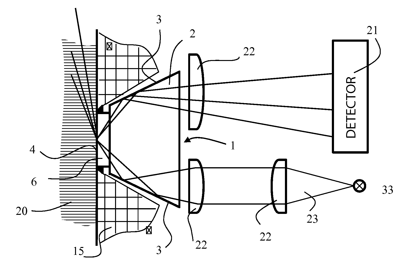
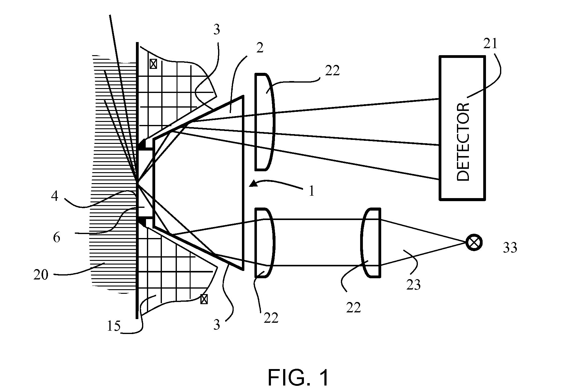
[0031]Referring now to the figures of the drawings in detail and first, particularly to FIG. 1 thereof, there is shown a principle structure of a measuring device according to the present invention, in this case of an Abbe-refractometer for measuring a critical angle of a total reflection. A deflecting prism 1 is inserted tightly with its boundary surface or its measuring surface 4 against a medium 20 to be examined, which is located, for example, in a process pipe, in a recess 30 in a wall 15 of the process pipe. For the measurement, electromagnetic radiation 23 of predetermined wave lengths is radiated from a radiation source 33 into the deflecting prism 1, if necessary, via collimators 22. In addition, filters can also be installed in the beam path, in order to select or mask out targeted wave length ranges and / or polarization directions. The radiation 23 emanating from the radiation source 33 is radiated on the side-surfaces or beam surfaces 3 or the side media boundary surfaces...


PUM


Abstract

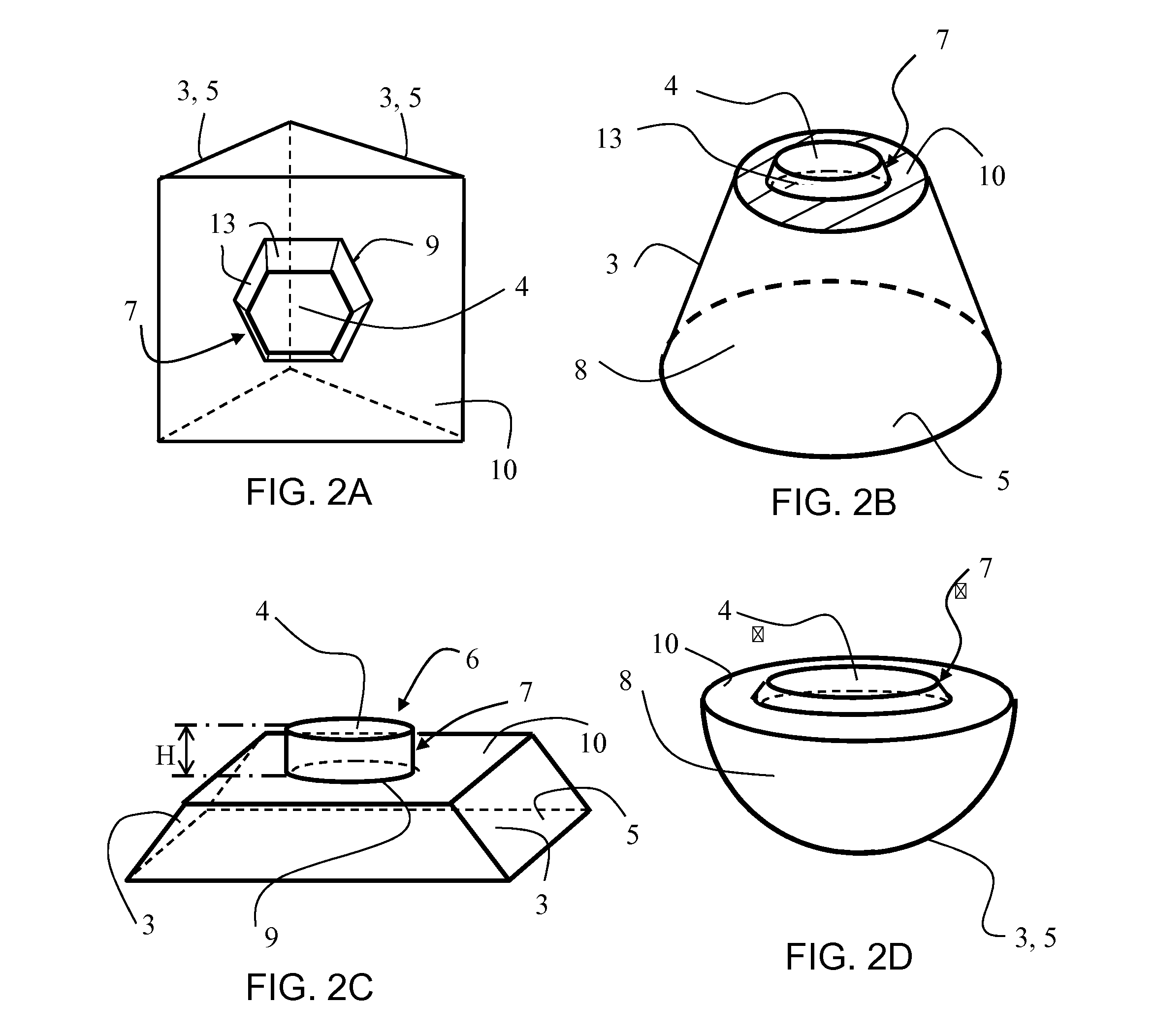
A deflecting prism for electromagnetic radiation, in particular for refractometer- and / or ATR-measurements, is part of a measuring configuration. The deflecting prism has a body produced in one piece from a mono-crystal. The body has at least two beam conductive surfaces on a side of the body opposite each other or circumferentially about the body and a measuring surface lying between the beam conductive surfaces or surrounded by the latter. The body further has at least one beam entry surface or a beam exit surface. Accordingly, the measuring surface lies on an elevation formed on the body, which crosses over via a ledge surrounding the elevation into the remaining part of the body. On the remaining part, the beam conductive surfaces and / or the beam entry surface or exit surface lie.

Description

CROSS-REFERENCE TO RELATED APPLICATION[0001]This application claims the priority, under 35 U.S.C. §119, of Austrian application A50266 / 2014, filed Apr. 9, 2014; the prior application is herewith incorporated by reference in its entirety.BACKGROUND OF THE INVENTIONField of the Invention[0002]The invention relates to a deflecting prism for electromagnetic radiation according to the preamble of the main patent claim. Such prisms are used particularly for the examination of fluids, in particular, in attenuated total reflections (ATR) measuring devices or refractometers. It is of special importance thereby, that the deflecting prism is used as an optical element of a measuring device or a measuring arrangement hermetically sealed into the housing of the measuring device or into the housing wall of a pipeline conducting the medium to be examined.[0003]Such deflecting prisms and measuring devices are needed in different process applications in the food industry, in the chemical industry, i...

Claims


Application Information

Patent Timeline
IPC IPC(8): G02B5/04G01J1/04G01N21/552
CPCG02B5/04G01N2201/068G01J1/0477G01N21/552G01N2021/434G02B1/02G01N21/43
Inventor CAGRAN, CLAUSIMRE, MICHAELHEPPNER, ULRICH
Owner ANTON PAAR
Learn More