Ultrasound imaging system and method for image guidance procedure

a technology of ultrasound imaging and ultrasound guidance, applied in ultrasonic/sonic/infrasonic diagnostics, instruments, organ movement/change detection, etc., can solve the problems of limiting the use of flow imaging techniques, difficult to keep invasive medical devices, and missing invasive medical devices (e.g. needles) in the intended anatomical region, etc., to achieve increased or sufficient frame rate, the effect of increasing or sufficient frame ra

Active Publication Date: 2015-10-15
KONINKLJIJKE PHILIPS NV
View PDF5 Cites 9 Cited by
  • Summary
  • Abstract
  • Description
  • Claims
  • Application Information

AI Technical Summary

Benefits of technology

[0007]It is an object of the present invention to provide an improved ultrasound imaging system, in particular with increased or sufficient frame rate. It is a further object of the present invention to pr

Problems solved by technology

A slow frame rate and accordingly a delayed ultrasound image feedback may result in the invasive medical device (e.g. needle) missing in the intended anatomical region.
This can limit the use of any flow imaging techniques, which require the acquisition of many pulse-echo events per imaging line, such as for example color flow imaging or also called color Doppler imaging, during an ultrasound image guiding procedure.
In p

Method used


Image

  • Ultrasound imaging system and method for image guidance procedure
  • Ultrasound imaging system and method for image guidance procedure
  • Ultrasound imaging system and method for image guidance procedure

Examples


first embodiment

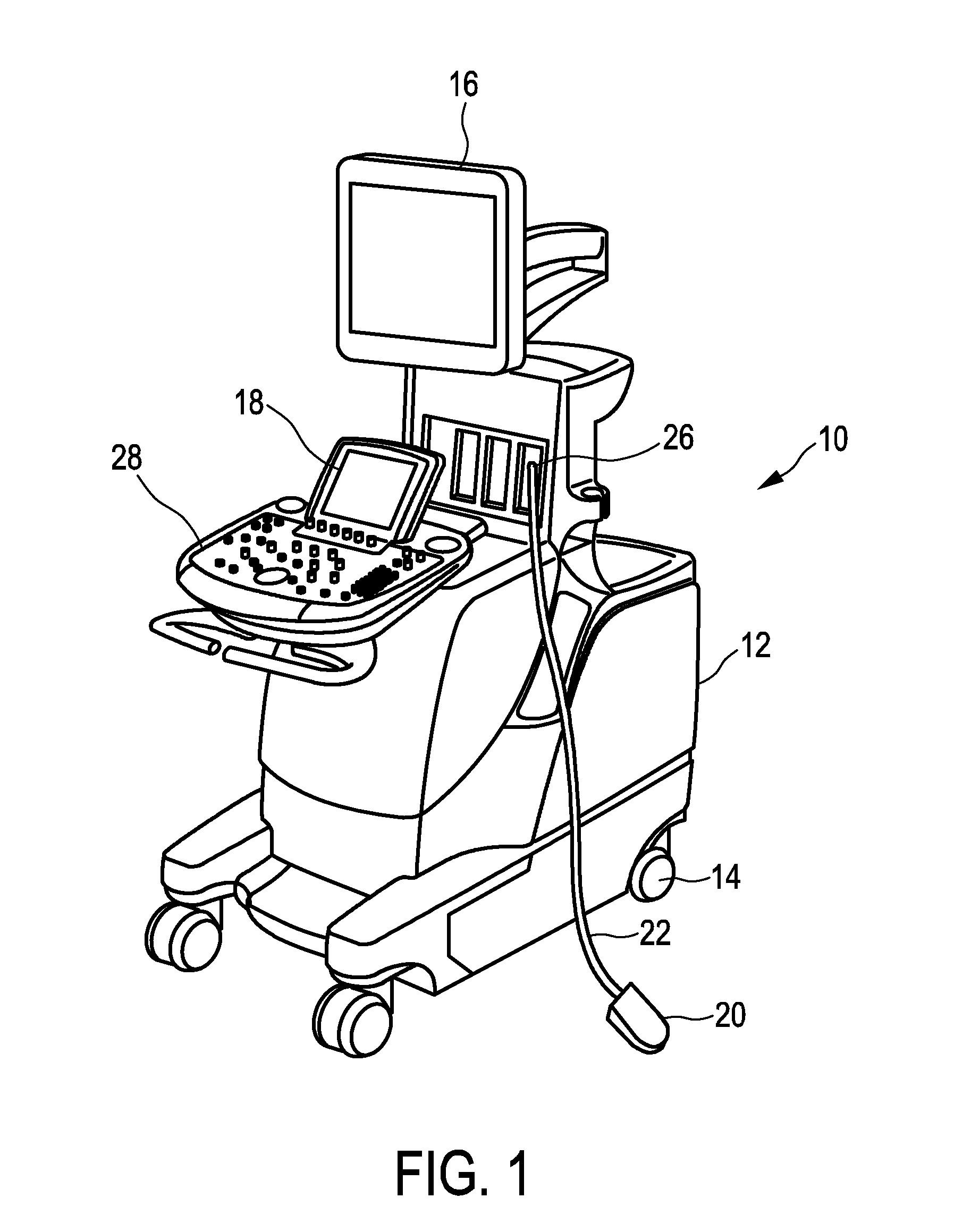
[0045]FIG. 3 shows a block diagram of an ultrasound imaging system 10 according to a The ultrasound imaging system 10 comprises an ultrasound probe 20 having a transducer array 21 configured to provide an ultrasound receive signal. The transducer array 21 can in particular be a 2D transducer array. The ultrasound imaging system 10 of FIG. 1 comprises a beamformer 25 connected to the ultrasound probe 20 and its transducer array. The beamformer 25 receives an ultrasound receive signal or data from the transducer array 21 and performs beamforming. In this way many 2D scans or frames that lie one next to one another are acquired which are then sent to a B-mode volume processing unit 30 to form a 3D-volume 31 of data. Thus, in the embodiment shown in FIG. 3, as well as in the following embodiments, electronic scanning of the volume in the anatomical region is used. However, it will be understood that the system could alternatively also use mechanically scanning.

[0046]As mentioned, the u...

second embodiment

[0059]FIG. 6 shows a block diagram of an ultrasound imaging system in which the vessels or vasculature in the anatomical region are identified using a 3D flow imaging technique. In the embodiment of FIG. 6, the ultrasound imaging system 10 additionally comprises a 3D flow processing unit 78 configured to generate 3D flow data 79 based on the ultrasound receive signal, and a flow image processing unit 80 configured to generate the 3D vessel map 51 based on the 3D flow data 79. 3D flow data 79 (or also called flow volume) can be generated in that the transducer array 21 transmits multiple ultrasound pulses for each line in order to estimate the flow at that line. Then, the acquisition of these lines is swept across the volume. The number of ultrasound pulses may be increased. This increases the sensitivity, but also reduces the frame rates. For example, the 3D flow processing unit 78 can be configured to generate the 3D flow data 79 using a color flow technique, a Color Power Angio (...


PUM


Abstract

The present invention relates to an ultrasound imaging system (10) comprising an ultrasound probe (20) having a transducer array (21) configured to provide an ultrasound receive signal. The system further comprises a B-mode volume processing unit (30) configured to generate a B-mode volume (31) based on the ultrasound receive signal, and a B-mode image processing unit (40) configured to provide a current B-mode image (41) based on the B-mode volume (31). The system further comprises a memory (50) configured to store a previously acquired 3D-vessel map (51). Also, the system comprises a registration unit (60) configured to register the previously acquired 3D-vessel map (51) to the B-mode volume (31) and to select a portion (61) of the 3D-vessel map corresponding to the current B-mode image (41). Further, the system comprises a display configured to display an ultrasound image (71) based on the current B-mode image (41) and the selected portion (61) of the 3D-vessel map (51). The present invention further relates to a method for providing such ultrasound image with vessel information and a corresponding computer program.

Description

FIELD OF THE INVENTION[0001]The present invention relates to an ultrasound imaging system and a method for providing an ultrasound image with vessel information, in particular for use in an image guidance procedure. The present invention further relates to a computer program for implementing such method.BACKGROUND OF THE INVENTION[0002]In three-dimensional (3D) ultrasound imaging, also called volume imaging, the acquisition of a 3D-image is accomplished by conducting many two-dimensional (2D) scans that slice the volume of interest in an anatomical region. Hence, a multitude of 2D-images is acquired that lie one next to one another. This multitude of 2D-images together forms a 3D-volume of data. By proper image processing, a 3D-image of the volume of interest can be built out of the 3D-volume of data. The 3D-image can then be displayed in a proper form on a display for the user of the ultrasound imaging system.[0003]Ultrasound imaging is commonly used to image the insertion, use or ...

Claims


Application Information

Patent Timeline
IPC IPC(8): G06T15/08G06T11/00
CPCG06T11/003G06T15/08A61B8/06A61B8/0841A61B8/0891A61B8/4245A61B8/4263A61B8/4405A61B8/461A61B8/466A61B8/467A61B8/483A61B8/488A61B8/5246A61B8/5261A61B2034/2063A61B34/20A61B2034/2051A61B2034/2061A61B2034/2065A61B2090/378A61B8/00A61B8/08G06T7/00
Inventor NG, GARY CHENG-HOWJAGO, JAMES ROBERTSONROBINSON, ANDREW LEE
Owner KONINKLJIJKE PHILIPS NV
Why Eureka
Try Eureka