Dis-Bond Membrane for a Lined Pressure Vessel

Active Publication Date: 2015-10-22
THE BOEING CO
View PDF16 Cites 5 Cited by
  • Summary
  • Abstract
  • Description
  • Claims
  • Application Information

AI Technical Summary

Benefits of technology

[0007]The disclosed embodiments provide a method of fabricating a pressure vessel having a dis-bond membrane between an inner liner and an outer structural wall. The dis-bond membrane prevents bonding between the inner liner and the structural outer wall. In embodiments where the outer wall is formed of a thermoset and the inner liner is mad

Problems solved by technology

For example, where the liner is formed of a thermoplastic and the structural outer wall is formed of a thermoset that is in contact with the thermoplastic, undesired stress concentrations in the vessel may result from co-mingling of the thermoplastic with th

Method used


Image

  • Dis-Bond Membrane for a Lined Pressure Vessel
  • Dis-Bond Membrane for a Lined Pressure Vessel
  • Dis-Bond Membrane for a Lined Pressure Vessel

Examples


Embodiment Construction

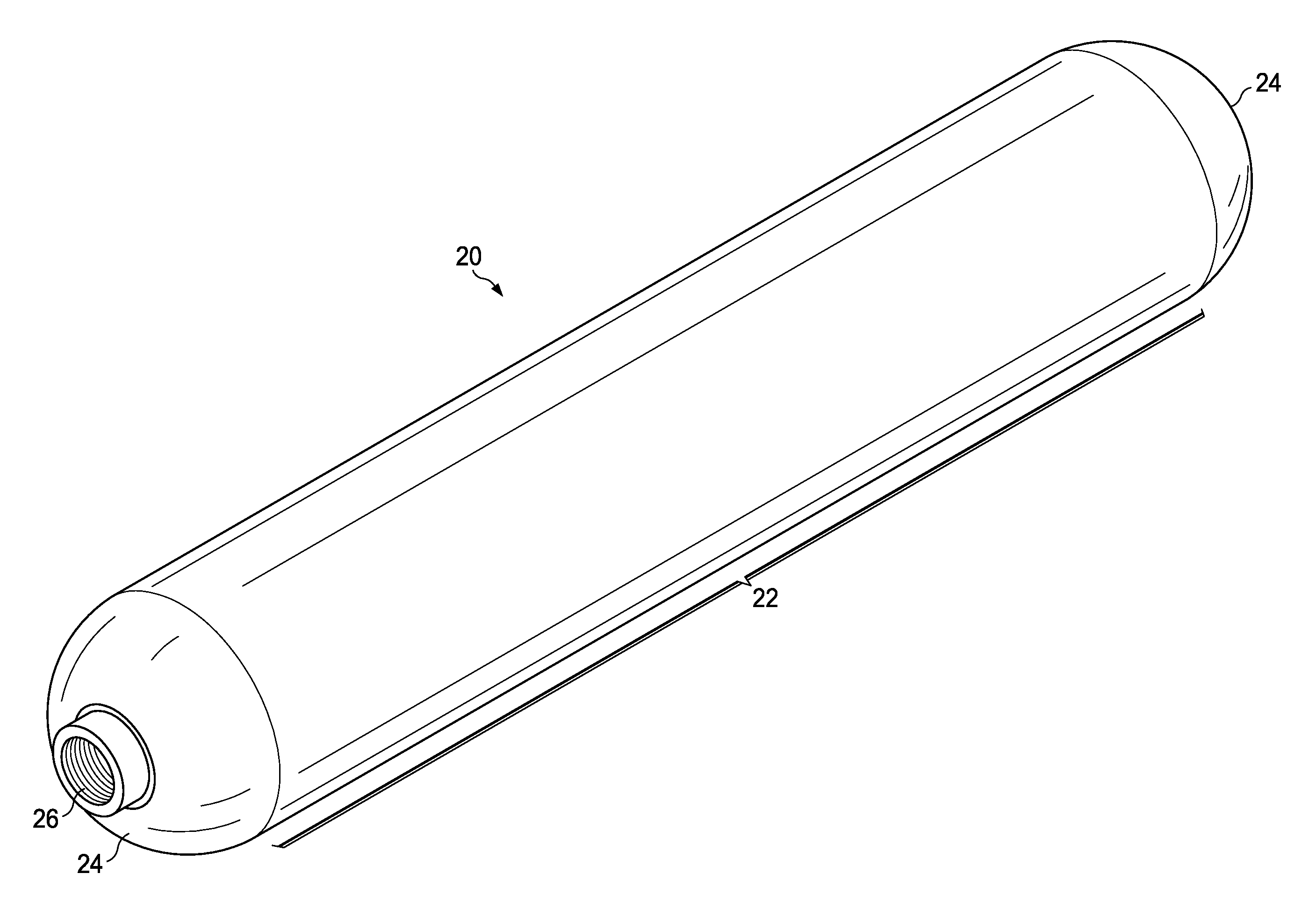
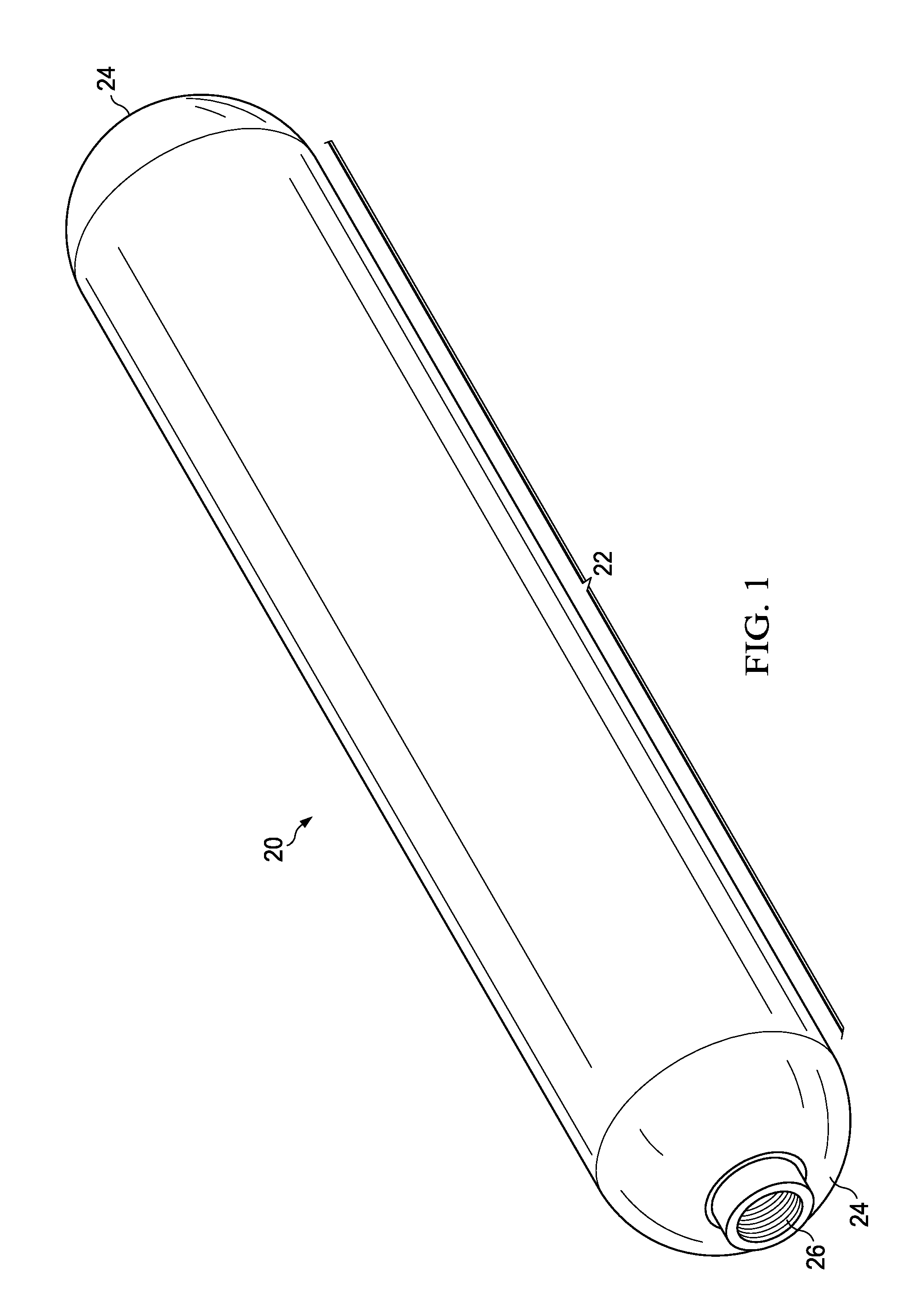
[0023]Referring first to FIG. 1, a pressure vessel 20 comprises a substantially constant cylindrical body 22 and dome-shaped outer ends 24. One or both of the dome-shaped ends 24 may have a boss 26 adapted to receive a suitable fitting (not shown) that may be used to either fill the pressure vessel 20 with a gas or draw gas from the pressure vessel 20.

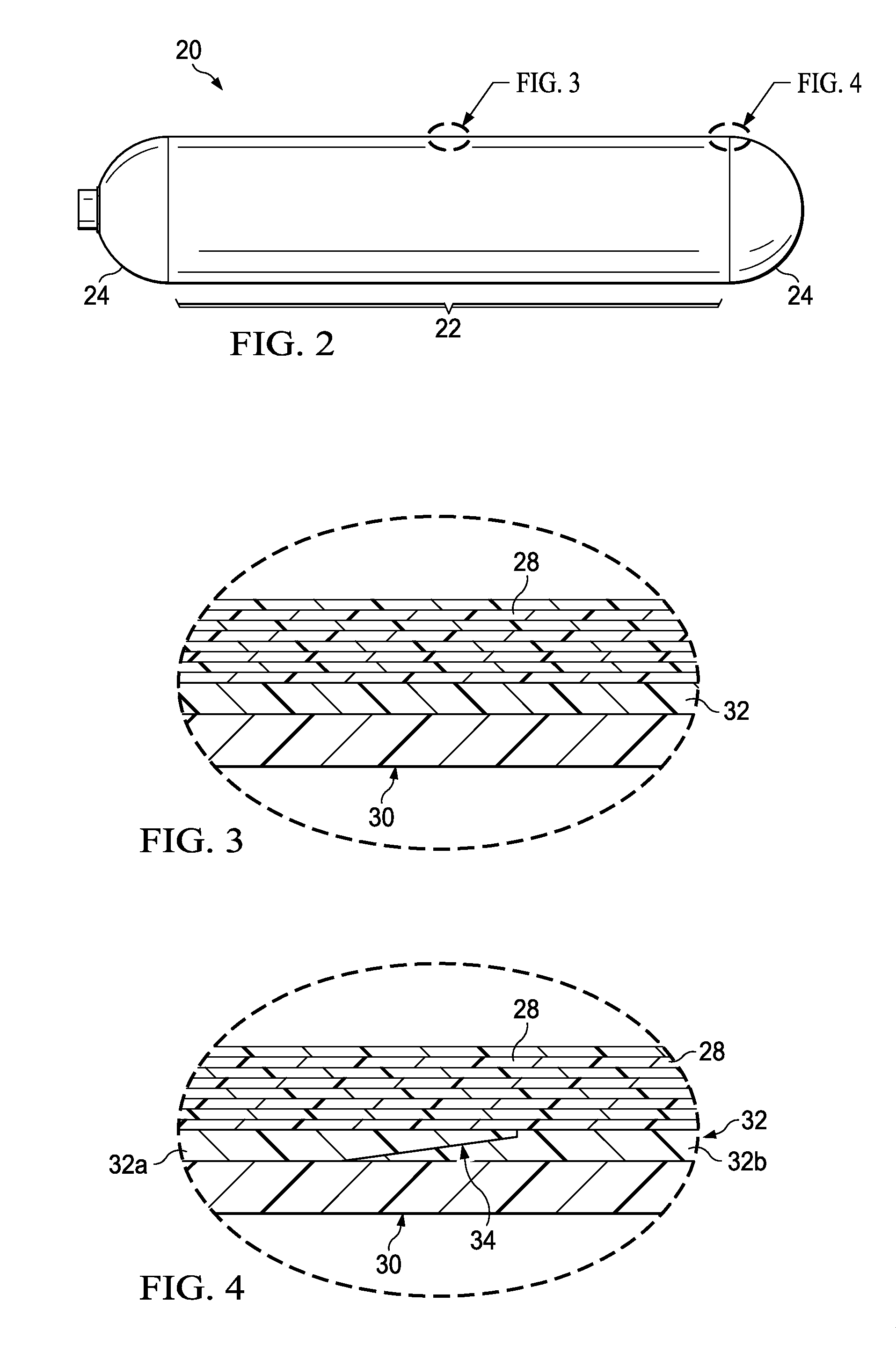
[0024]Referring now also to FIGS. 2, 3, 4, 5 and 6 the pressure vessel 20 broadly comprises an inner liner 30 surrounded by a composite structural outer wall 28. In one embodiment, the structural outer wall 28 may comprise a constant cylinder section 44 (FIG. 5), and separate dome caps 42 that are overlapped (see FIG. 6) at 34 by the constant cylinder section 44. The constant cylinder section 44 and the dome caps 42 are formed of a thermosetting prepreg tape or tows. In other embodiments however, the structural outer wall 28 may comprise a single composite structure formed by wrapping prepreg tape or tows around the entire outer surfac...


PUM

PropertyMeasurementUnit
Temperatureaaaaaaaaaa

Abstract

A dis-bond membrane prevents co-mingling between a thermoplastic liner and a fiber reinforced thermoset outer wall of a pressure vessel during thermal curing of the outer wall.

Description

BACKGROUND INFORMATION[0001]1. Field[0002]The present disclosure generally relates to composite pressure vessels having liners, and deals more particularly with a dis-bond membrane that prevents bonding between the composite pressure vessel and the liner.[0003]2. Background[0004]Several types of constructions are known for high pressure vessels used to store liquids or gases such as hydrogen, for example. In one type of construction, commonly referred to as a Type IV pressure vessel, a plastic inner liner is surrounded by an outer structural wall formed by a fiber reinforced resin wrap. These types of pressure vessels are typically cylindrical in shape with domed ends. The pressurize vessels are cyclically pressurized, both as part of the fabrication process, and later, when placed in service.[0005]The mechanical performance of the pressure vessel may depend upon the compatibility of the materials used for the liner and structural outer wall, and the processes used to fabricate the ...

Claims


Application Information

Patent Timeline
IPC IPC(8): B65D23/02B32B3/02
CPCB65D23/02B32B2439/40B32B3/02B32B7/12B32B27/08B32B27/20B32B27/288B32B27/32B32B27/36B32B27/38B32B1/02B32B2262/106B32B2307/7242Y10T428/24744Y10T428/24752
Inventor MILLER, RICHARD A.
Owner THE BOEING CO
Why Eureka
Try Eureka