
Device for the study of self-contained inertial vehicular propulsion

a technology a device, which is applied in the field of devices for the study of inertial vehicular propulsion, can solve the problems of intriguing problems faced by clockmakers, and achieve the effects of high internal angular speed, low vibration characteristic, and high degree of efficiency

Inactive Publication Date: 2015-10-22
GUTSCHE GOTTFRIED J
View PDF10 Cites 6 Cited by
  • Summary
  • Abstract
  • Description
  • Claims
  • Application Information

AI Technical Summary

Benefits of technology

The invention is an inertial propulsion system that has high efficiency and low vibration characteristics. It can achieve high internal angular speeds.

Problems solved by technology

Clockmakers were confronted by an intriguing problem.

Method used


Image

  • Device for the study of self-contained inertial vehicular propulsion
  • Device for the study of self-contained inertial vehicular propulsion
  • Device for the study of self-contained inertial vehicular propulsion

Examples


Embodiment Construction

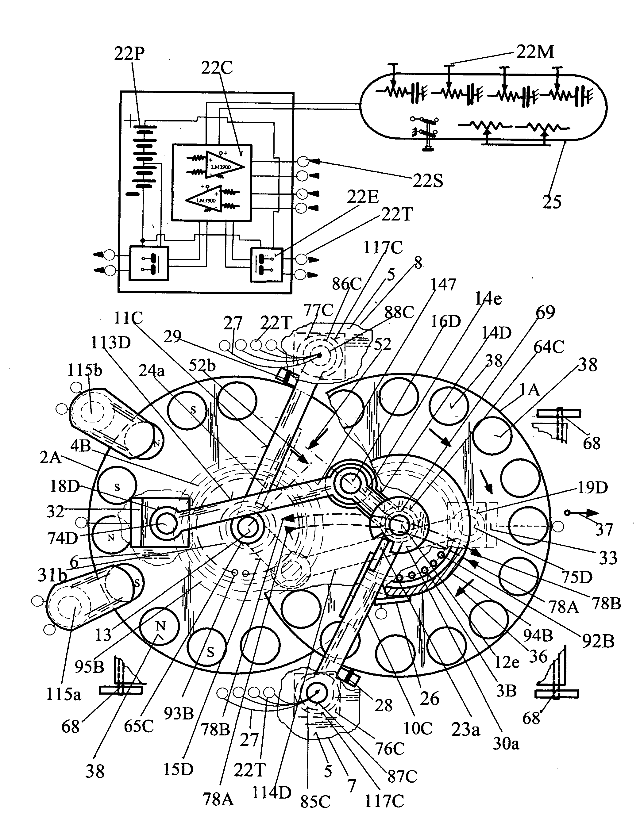
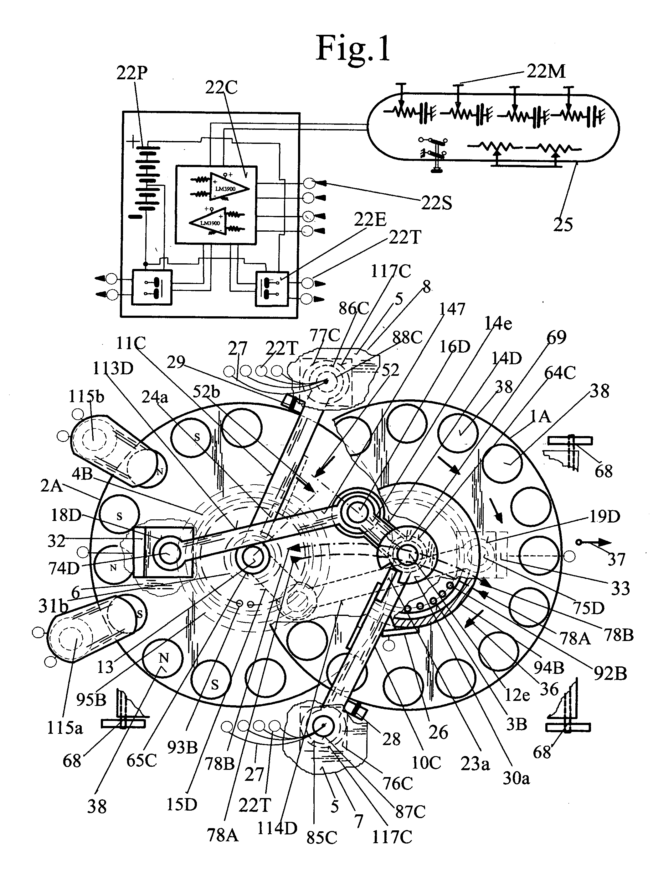
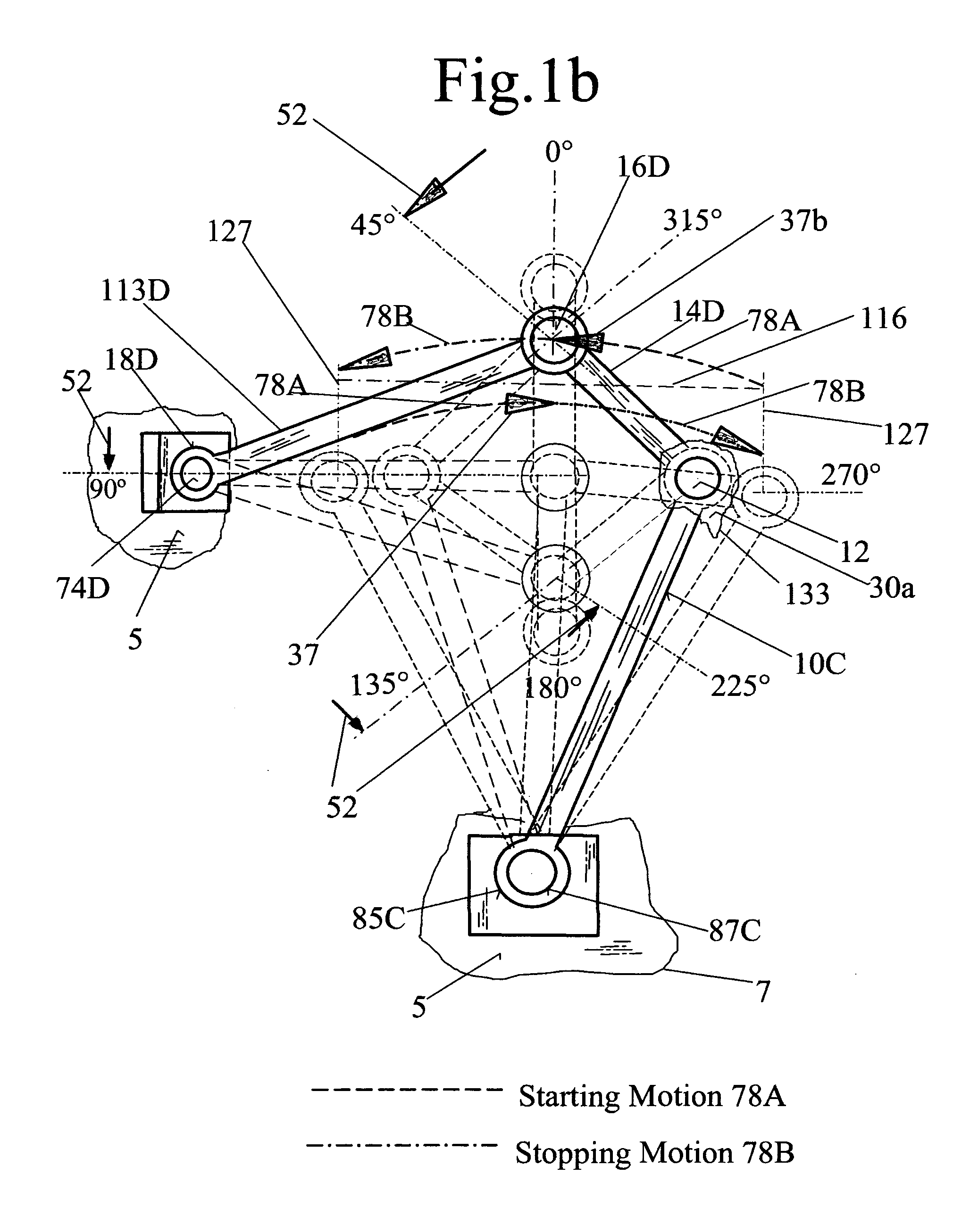
[0032]Referring to FIG. 1, FIG. 1b, FIG. 1c FIG. 1d and FIG. 2; the self-contained propulsion device comprising pairs of flywheels, 1A, 2A, having parallel axial orientation, a moment of inertia 104, a straight line motion inertia 106 and a net straight line displaceable axial spacing 116. The flywheel 1A,2A rotation 36 is around the central shaft 12,13 by means of a bearing 69,70. Each individual flywheel of the flywheel pair, in comparison to each other's central shaft axis, have a straight line mutual separating motion 78A followed by a re-approaching motion 78B and have opposite direction of rotation 36; therefore, the straight line motion of the flywheel pair is a kinetic energy 106 dependent mutual time sequential diametrically opposing cyclic alternating straight line motion. The flywheel motions comprising a straight line motion in direction 37 and opposite 37b of vehicular travel direction. The flywheel alternating straight line motion cycle consists of a starting motion 78...


PUM


Abstract

A novel device for the study of self-contained timely sequential vehicular inertial thrust drive is presented, comprising a tandem mechanical frequency modulated oscillator using the combined effort of straight line and rotational inertial reluctance contained in the mass of flywheels. The flywheels are having straight line parallel axial orientation, opposite freewheeling rotation and opposite alternate cyclic free flowing non-uniform reciprocal motion in union with vehicular travel by means of a straight line to rotational-coupled motion. The straight line to rotational-coupled motion accomplishes the cyclic realignment of the flywheel motion to combine the straight line and rotational motion into one timely gradient vector sum motivating thrust drive. The free flowing straight line and rotational inertial reluctance of the flywheel mass is used as the motivating drive kinetic energy by timely non-uniform mutual reciprocal separation against the device mass and the freewheeling rotational inertial reluctance of the flywheel's mass moment is used to absorb rotational mutually reciprocal contrary rotational kinetic energy. An integral motor-generators rotor contained within each flywheel accumulates rotational kinetic energy subsequently used for the propulsion of the device and is used to obtain the frequency modulation and non-uniform motions. The motor-generator with attached rotational-to-reciprocating transmission is directing the accumulated kinetic energy non-uniformly mutually reciprocally into the device in direction of vehicular travel and into the free flowing straight line and rotational flywheel mass. The cyclic sum of all mutual and reciprocal actions is a closed loop cycle with two self-contained superior centripetal inertial thrust drives.

Description

[0001]This is a Continuation-in-part (C.I.P) specification for the CIP application Ser. No. 12 / 802,388FIELD OF THE INVENTION[0002]The present invention relates to a device for developing a self-contained timely sequential potential energy work output thrust drive in a predetermined direction. The invention is using known engineering principles published in the “Kurt Gieck Engineering Formula Book” depicted in FIG. 10, wherein the applicable book sections are indicated in brackets; in particular, it applies to the simultaneous combined kinematic effort of variable rotational 105 and strait line motion kinetic energy 106 contained in pairs of flywheels inertial mass motions, wherein a regenerative drive under control of machine logic provides the flywheels' variable kinetic energy 103. Furthermore, the invention applies to the physics principle of Newton's derivation of the gravitational pendulum, the proposition XXIV XIV published with his second principia book in 1713; wherein the d...

Claims


Application Information

Patent Timeline
IPC IPC(8): F03G3/08F16H33/08H02K7/065
CPCF03G3/08F16H33/08H02K7/065F03G7/10F03G7/125
Inventor GUTSCHE, GOTTFRIED J.
Owner GUTSCHE GOTTFRIED J
Learn More