
Thermal Management for a Super Capacitor Power Supply

a super capacitor and power supply technology, applied in the field of welding, can solve the problems of high weld current, significant temperature rise, and inability to meet the needs of ultra-capacitors, and achieve the effect of low electrical resistan

Inactive Publication Date: 2015-10-29
SUNSTONE ENG
View PDF6 Cites 7 Cited by
  • Summary
  • Abstract
  • Description
  • Claims
  • Application Information

AI Technical Summary

Benefits of technology

This patent describes a power supply for a capacitive discharge welder that has an integrated thermal management system. The housing of the power supply allows for the integration of ultracapacitor thermal management with electrical connectivity and mechanical modularity. The patent also describes the design of thermal fin elements made of conductive material that serve as both thermal fins for removing waste heat and as an electrical path for reducing resistance. The thermal fin assembly can also be designed to be self-isolating, and an insulative outer shell can be added to create a wind tunnel and allow for stacking or mounting multiple power supply modules. The patent also mentions the use of a fan to direct airflow through the housing for cooling. Overall, this patent provides a solution for efficient thermal management and electrical connectivity for capacitive discharge welders.

Problems solved by technology

However, CD welders are not without certain drawbacks and limitations that are directly related to the use of capacitors as a power source.
Ultra-capacitors can experience high weld currents and can have a significant temperature rise during the welding processes.

Method used


Image

  • Thermal Management for a Super Capacitor Power Supply
  • Thermal Management for a Super Capacitor Power Supply
  • Thermal Management for a Super Capacitor Power Supply

Examples


Embodiment Construction

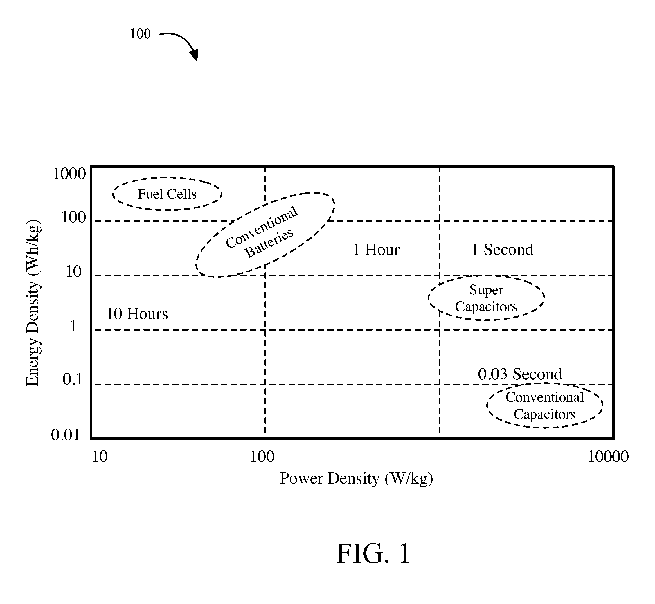
[0030]A “super capacitor,” also known as an electric double-layer capacitor or “ultra-capacitor,” can be defined as an electrical component characterized by both double-layer capacitance and pseudocapacitance. Presently known super capacitors may have up to 10,000 times the capacitance of a conventional electrolytic capacitor and anywhere from 10 to 100 times the power density of a conventional battery. The relative ratio of power density and energy density for various power sources is illustrated in FIG. 1. As shown in FIG. 1, super capacitors are capable of delivering significantly higher performance for applications where higher levels of energy and power density are desirable.

[0031]The high energy density combined with high power density of super capacitors allows very large amounts of energy to be stored in a super capacitor with rapid charge and discharge cycles. A welder with a capacitive power source (e.g., a typical CD welder or Linear DC welder) that would typically be cap...


PUM

PropertyMeasurementUnit
energyaaaaaaaaaa
energyaaaaaaaaaa
energyaaaaaaaaaa

Abstract

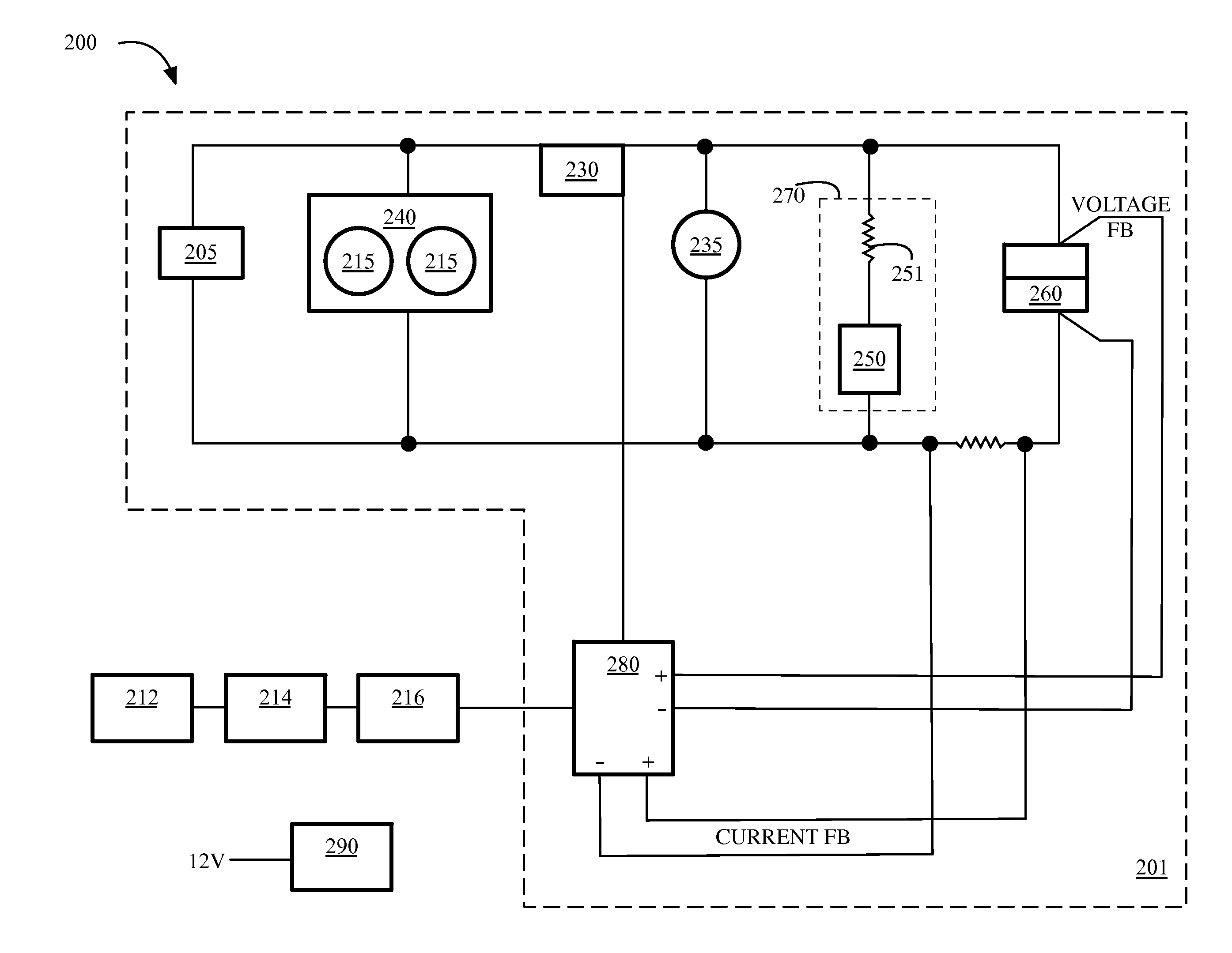
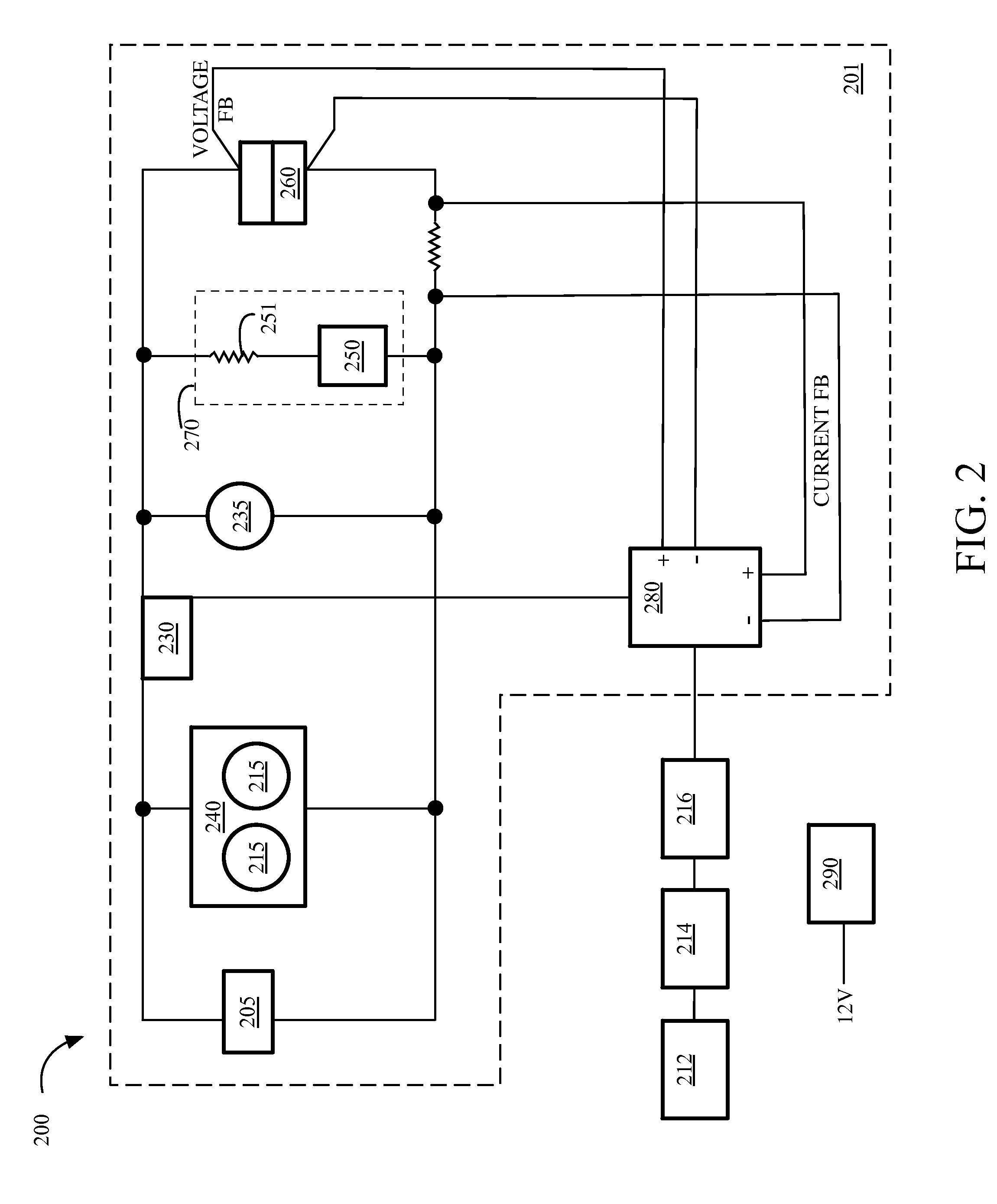
A power supply assembly, suitable for use in conjunction with a capacitive discharge welder, comprises an integrated thermal management system. The housing of the power supply assembly allows the integration of ultra-capacitor thermal management with electrical connectivity and mechanical modularity. In the most preferred embodiments of the present invention, aluminum (or other conductive material, such as copper, etc.) channels are shaped and arranged to both act as thermal fin elements for the removal of waste heat while simultaneously serving as an electrical path with a relatively low electrical resistance. The thermal fin assembly may comprise self-isolating insulation elements or the thermal fin elements may be electrically isolated from each other by an electrically insulating material. Airflow within the housing may be directed via fan or other method into the ultra-capacitor wind tunnel to remove heat from the capacitor cylinder itself as well as the thermal conductive fin elements.

Description

CROSS REFERENCE TO RELATED APPLICATIONS[0001]This application is a continuation-in-part of U.S. patent application Ser. No. 14 / 084,575, which application was filed on Nov. 19, 2013, and which application is currently pending and which application is incorporated herein by reference.BACKGROUND OF THE INVENTION[0002]1. Technical Field[0003]This invention relates to the field of welding and more particularly relates to thermal management systems for welding equipment.[0004]2. Background Art[0005]Capacitive discharge welders (CD welders), also called capacitive resistance or capacitor discharge spot welders, have been in use in a variety of industries for many years. These welding systems are used to produce quick burst of energy for controlled energy transfer into a specific weld spot. CD welders utilize capacitors, with an electrical circuit charging the energy in the capacitors to the desired level. The total capacitor energy is typically released in a very short time to the weld loc...

Claims


Application Information

Patent Timeline
Patent Type & Authority Applications(United States)
IPC IPC(8): B23K11/26G05F3/16
CPCG05F3/16B23K11/26B23K37/003B23K11/36H01G11/18Y02E60/13
Inventor ASTLE, AARON A.
Owner SUNSTONE ENG
Learn More