Trending machine health data using RFID transponders

a technology of trending machine health data and transponder, which is applied in the field of machine condition monitoring system, can solve the problems of affecting the safety of individuals, the trend is not as simple as it sounds, and the problem of rapid detection of problems, so as to reduce the time and low cost

Inactive Publication Date: 2015-10-29
AB SKF
View PDF6 Cites 29 Cited by
  • Summary
  • Abstract
  • Description
  • Claims
  • Application Information

AI Technical Summary

Benefits of technology

[0053]The integration of an RFID transponder into a machine conditioning system provides several advantages over the currently used rout based inspection programs. As presented in the background, route based inspection programs introduce a variety of limitations. The introduction of RFID transponders into the machine condition monitoring system enables wireless near field communication between the RFID transponder and an associated RFID reader. This reduces time for a technician

Problems solved by technology

Unscheduled downtime can impact productivity of the machine and in more critical installations, could impact safety of individuals, property, and the like that rely upon the continuous operation of the machine.
Unfortunately, trending is not as simple as it sounds.
Alternately if a plant had many machines, and all parameters of those machines were being monitored continuously via an online “Condition Monitoring” system—then once again, problems would be quickly picked up on.
However, not all plants monitor all of their machine parameters using online systems, and so typically these facilities employ an “offline” condition monitoring system, and rely on their engineers to use a “route based” program to routinely check the health of each machine using offline test equipment.
Furthermore, “route based” inspection programs rely upon the use of complex and expensive handheld monitoring equipment: equipment, wh

Method used


Image

  • Trending machine health data using RFID transponders
  • Trending machine health data using RFID transponders
  • Trending machine health data using RFID transponders

Examples


Embodiment Construction

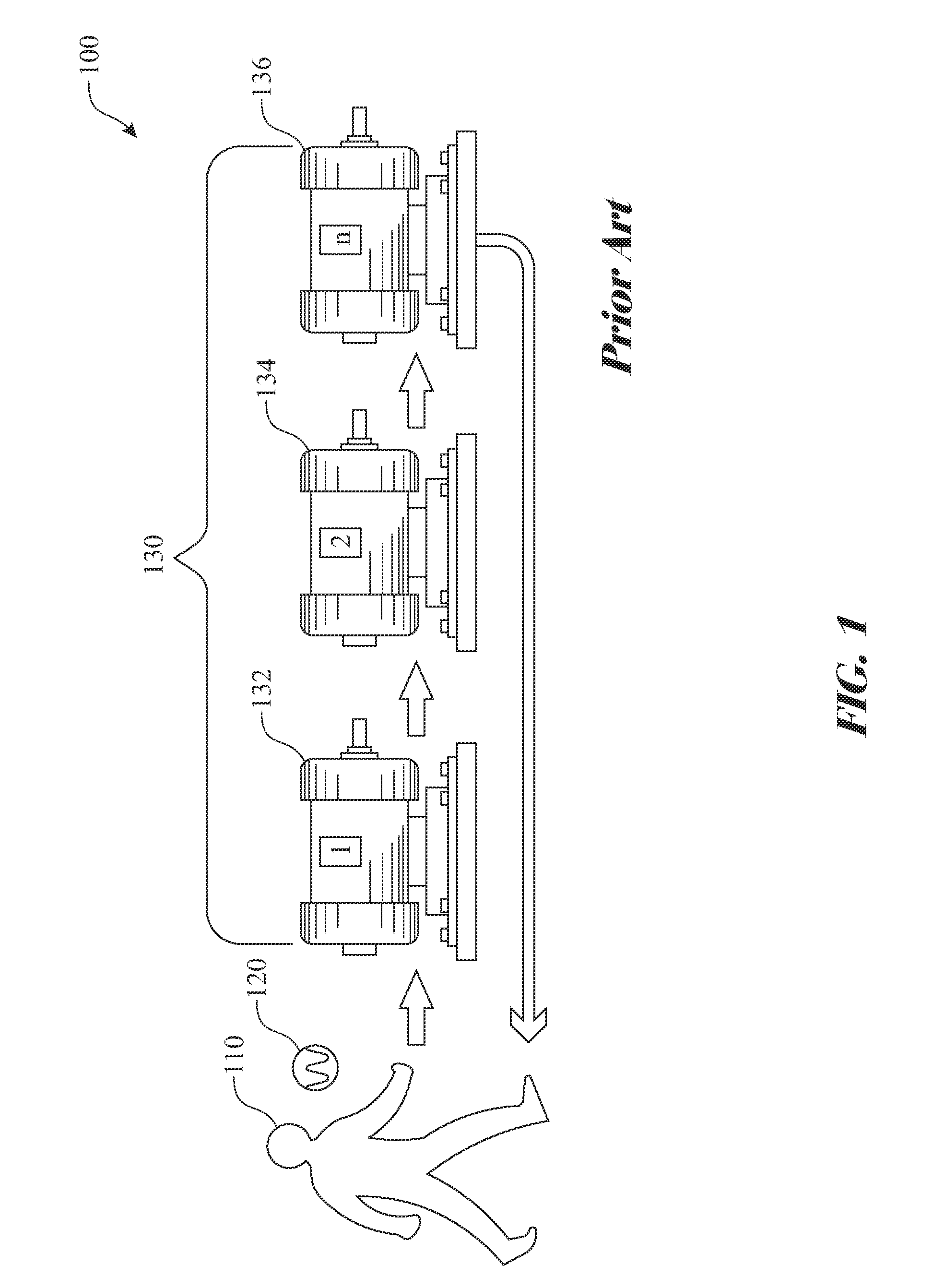
[0070]The following detailed description is merely exemplary in nature and is not intended to limit the described embodiments or the application and uses of the described embodiments. As used herein, the word “exemplary” or “illustrative” means “serving as an example, instance, or illustration.” Any implementation described herein as “exemplary” or “illustrative” is not necessarily to be construed as preferred or advantageous over other implementations. All of the implementations described below are exemplary implementations provided to enable persons skilled in the art to make or use the embodiments of the disclosure and are not intended to limit the scope of the disclosure, which is defined by the claims. For purposes of description herein, the terms “upper”, “lower”, “left”, “rear”, “right”, “front”, “vertical”, “horizontal”, and derivatives thereof shall relate to the invention as oriented in FIG. 1. Furthermore, there is no intention to be bound by any expressed or implied theo...


PUM


Abstract

A system for monitoring and recording health data associated with machine. The system employs a radio frequency identification (RFID) transponder, which is affixed to the machine. The system utilizes a digital memory component of the RFID transponder to record and maintain historical measurements to aid in determining machine condition trending. The RFID transponder interacts with a machine condition advisor (MCA), where the MCA obtains a configuration and historical data from the RFID transponder, queries sensors, collects data, transfers updated data to the RFID sensor, and determines and displays condition trending. Machine condition trending can be displayed in a graphical format. Warning or alarm levels can be established enabling the system to determine machine conditions warranting alerting a machine technician. Each machine condition trending can be independent of or associated with the associated warning or alarm level.

Description

FIELD OF THE INVENTION[0001]The present invention relates to a machine condition monitoring system. More specifically, the system employs a radio frequency identification (RFID) transponder affixed to the machine and a machine condition detector that interface with the RFID transponder to enable programmable monitoring and trend analysis of operating parameters of the monitored machine.BACKGROUND OF THE INVENTIONDiscussion of the Related Art[0002]Machine equipment uptime is critical in optimizing output and maintaining operation of the machine. Machines may be installed in critical systems requiring continuous uptime, with planned downtime for maintenance. Unscheduled downtime can impact productivity of the machine and in more critical installations, could impact safety of individuals, property, and the like that rely upon the continuous operation of the machine.[0003]One of the most important methods of determining the current health of any machine is by examining how measured para...

Claims


Application Information

Patent Timeline
IPC IPC(8): G08B21/18G06K7/10H04Q9/00
CPCG08B21/182G06K7/10366H04Q9/00G08B21/187G01M13/028G01M13/045G05B2219/31095G01H1/00G05B23/02G01M13/04
Inventor PINKERTON, ALEXANDER
Owner AB SKF
Why Eureka
Try Eureka