Slab laser and amplifier and method of use

a laser amplifier and laser beam technology, applied in the direction of optical resonator shape and construction, nuclear engineering, railway components, etc., can solve the problems of limiting the maximum size of yag, vanadate or gain crystals, inefficiency of beam extraction from gain materials, and limiting efficiency of existing lamp pump designs primarily. , to achieve the effect of improving efficiencies and power handling capabilities, high efficiency

Active Publication Date: 2015-10-29
STUART MARTIN A +1
View PDF4 Cites 18 Cited by
  • Summary
  • Abstract
  • Description
  • Claims
  • Application Information

AI Technical Summary

Benefits of technology

[0008]Also presented is the use of pump lamps that produce more photons in a usable spectrum than previous lamp designs based on noble gases. Cavity fluorescent filters have also been employed that convert a non-useful portion of the lamp output to useful pump bands at a rather high efficiency. This improves efficiencies and power handling capabilities.

Problems solved by technology

Such systems have become the standard with the limitation being the maximum size that YAG, Vanadate or gain crystals can be fabricated.
The limiting efficiency for the existing lamp pumped designs are primarily in two areas.
First is the inefficiency due to the fact that the emitting spectrum from the pump lamps typically does not match the excitation spectrum of the laser crystal material.
Second is in the inefficiency of the beam extraction from the gain material due to having the beam pass through no more than twice and incompletely fill the gain material.
These drawbacks have interfered with potential practical applications of the slab laser concept.

Method used


Image

  • Slab laser and amplifier and method of use
  • Slab laser and amplifier and method of use
  • Slab laser and amplifier and method of use

Examples


example application

[0096 System

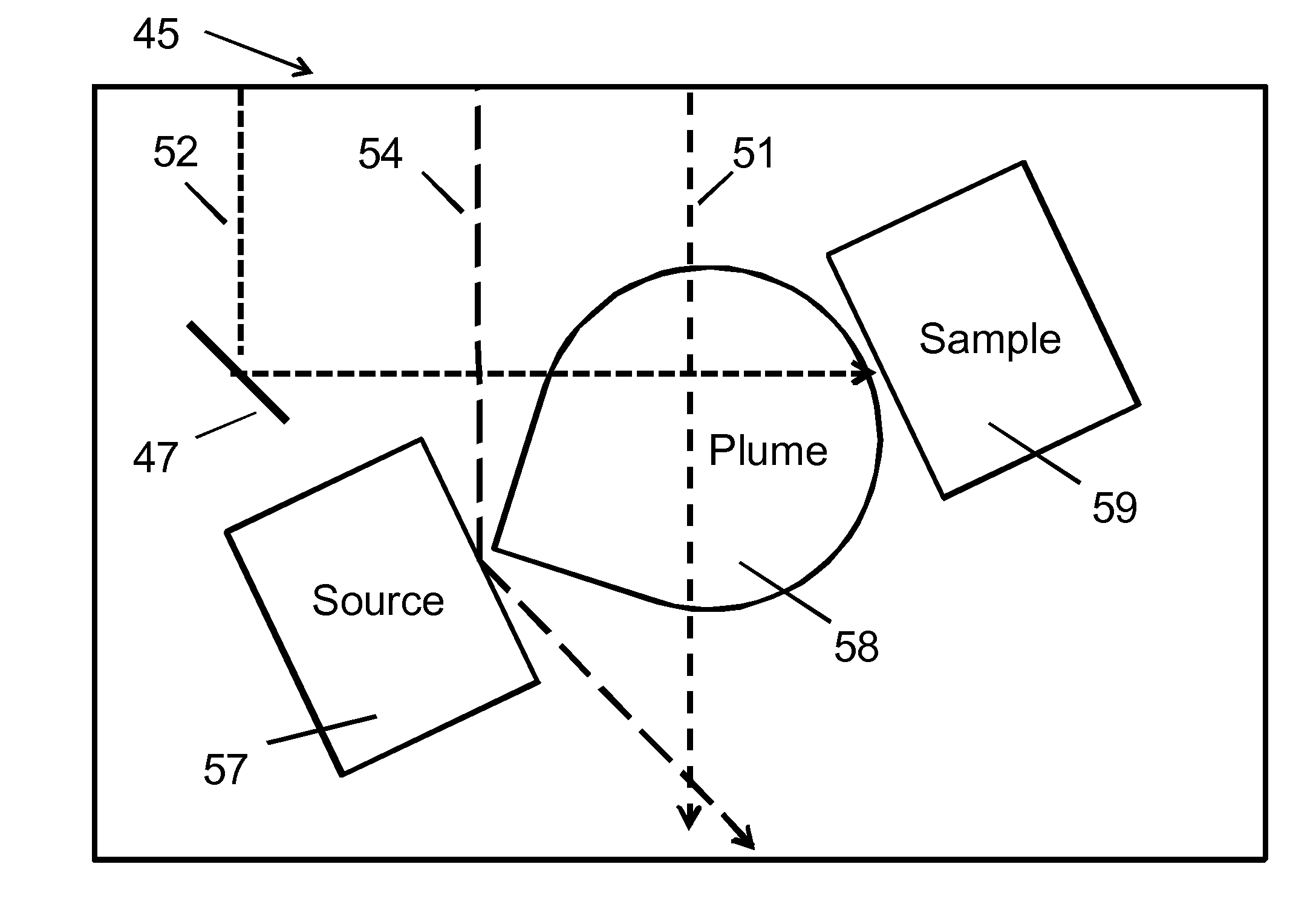
[0097]To illustrate how these components work and how they might be used, FIG. 14 shows a pulse from the source in a first seed laser 40 through the amplifier 42 and mirrors 48, 47 to its end point in the process chamber 45 and then we will repeat this for a second seed laser 41. The first seed laser 40 acts as a seed for the ultrafast amplifier chain 42. The pulse-length frequency and repetition rate is defined in this component according to the desired application. For example, it can produce a ½ nanosecond pulse, with this pulse having, e.g., a 100 nm wide bandwidth 750 nm to 850 nm, with pulses of, e.g., 312,500 per second being emitted. Alternatively, the fluorescence output bandwidth of Titanium Sapphire produces light from 650 nm to 1100 nm at the same rates as mentioned, allowing operation of the laser at those frequencies, where desirable.

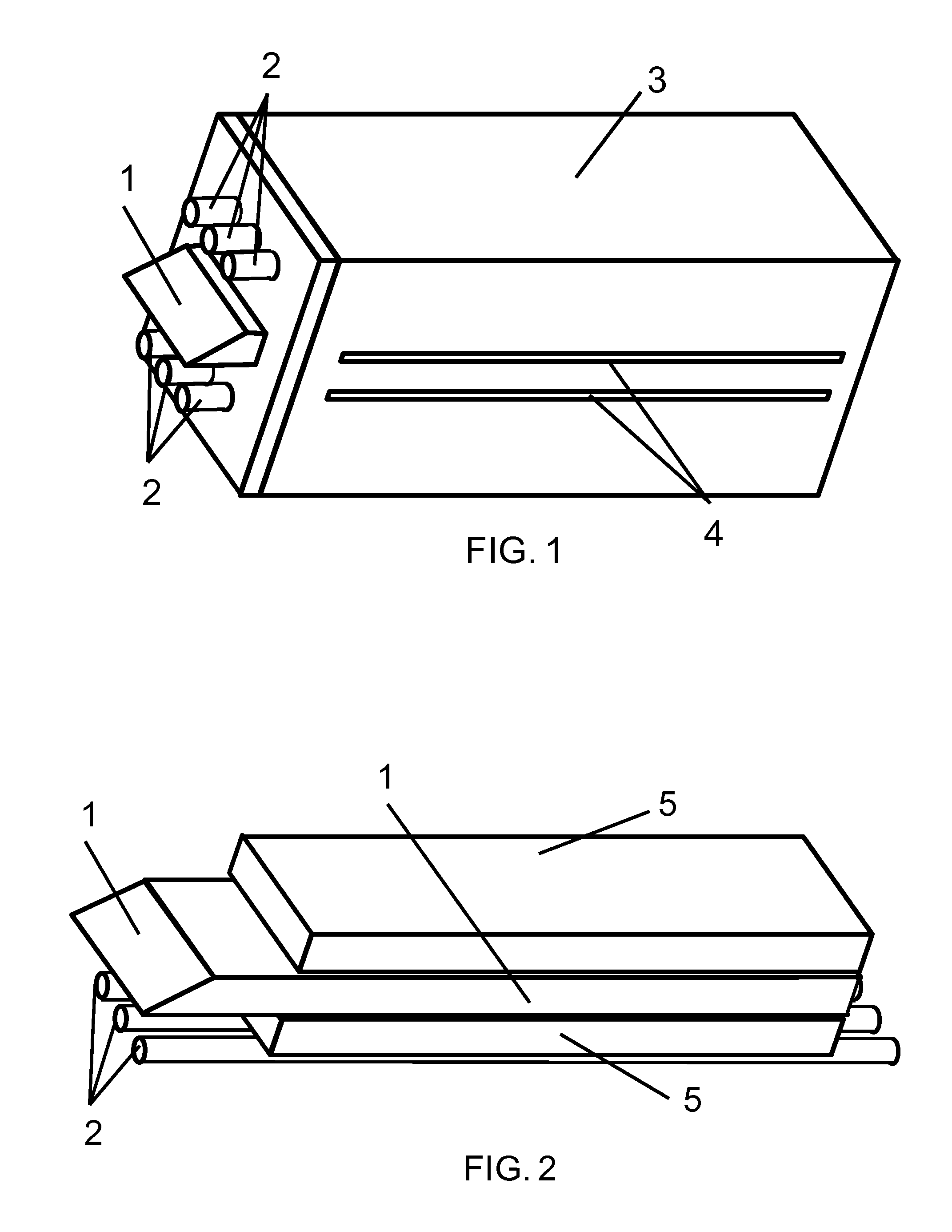
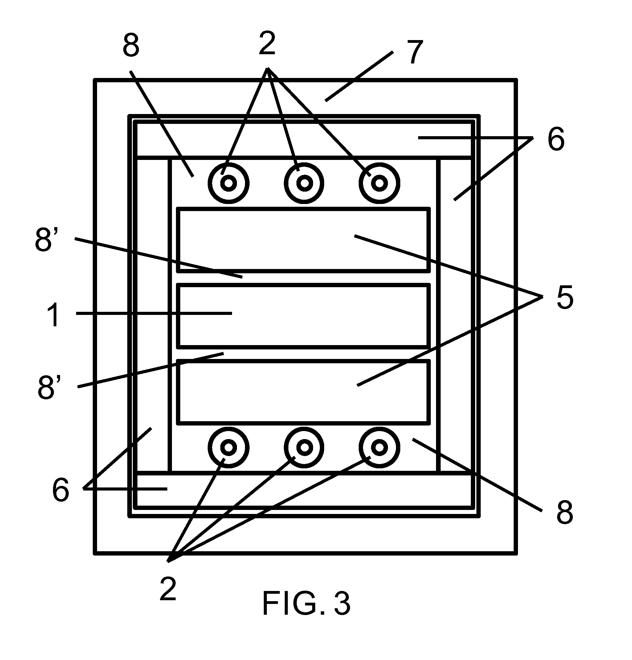
[0098]The amplifier chain can comprise of a series array of amplifier modules such as shown in FIG. 1 for an example module, ...


PUM

PropertyMeasurementUnit
pulse widthaaaaaaaaaa
angleaaaaaaaaaa
energy extraction efficiencyaaaaaaaaaa

Abstract

A slab laser and its method of use for high power applications including the manufacture of semiconductors and deposition of diamond and / or diamond-like-carbon layers, among other materials. A lamp driven slab design with a face-to-face beam propagation scheme and an end reflection that redirects the amplified radiation back out the same input surface is utilized. A side-to-side amplifier configuration permitting very high average and peak powers having scalability is also disclosed. Cavity filters adjacent to pump lamps convert the normally unusable UV portion of the pump lamp spectrum into light in the absorption band of the slab laser, thereby increasing the overall pump efficiency. The angle of the end reflecting surface is changed to cause the exit beam to be at a different angle than the inlet beam, thereby eliminating the costly need to separate the beams external to the laser with the subsequent loss of power.

Description

CROSS-REFERENCES TO RELATED APPLICATIONS[0001]This application claims the benefit of U.S. application Ser. No. 13 / 566,144 that was filed on Aug. 3, 2012, and is incorporated herein by reference.BACKGROUND[0002]This application relates generally to the field of Lasers and Laser Amplifiers. More specifically, the application relates to solid state laser amplifiers in the form of a slab which are pumped optically by lamps and where the laser beam enters through a Brewster angle facet and experiences multiple face to face bounces due to total internal reflection before exiting through the same face as that the beam entered.[0003]Generally, lamp driven slab lasers have existed for many years. The prior art is exemplified by General Electric's design of a Krypton arc lamp driven, face pumped, face to face multi-bounce, total internal reflection (TIR) Nd:Yag (Neodymium doped Yttrium Aluminum Garnet) slab. In General Electric's design, the Nd:Yag crystal was face pumped with Krypton arc lam...

Claims


Application Information

Patent Timeline
Patent Type & Authority Applications(United States)
IPC IPC(8): H01L21/02H01S3/06H01S3/04H01S3/042H01S3/08C23C16/27H01S3/16H01S3/23H01S3/11H01L31/024H01L31/18H01L21/3205H01S3/093
CPCH01L21/02266C23C16/27H01L21/02115H01L21/02194H01L21/02181H01L21/02183H01S3/0606H01S3/0407H01S3/042H01S3/08095H01S3/093H01S3/1623H01S3/1625H01S3/1666H01S3/1636H01S3/2333H01S3/11H01L31/024H01L31/18H01L21/3205H01S3/0615H01S3/1633H01S3/0621H01S3/092H01S3/0604G02B6/1223H01S3/0915H01S3/1601H01S3/163H01S3/2316C23C14/02C23C14/28H01S3/0071H01S3/08027H01S3/23H01S3/08086
Inventor STUART, MARTIN A.CUNNINGHAM, STEPHEN L.
Owner STUART MARTIN A
Why Eureka
Try Eureka