Method for molding two-piece blow molded hollow tank by using auxiliary male molds

Active Publication Date: 2015-11-05
YAPP AUTOMOTIVE PARTS
View PDF2 Cites 1 Cited by
  • Summary
  • Abstract
  • Description
  • Claims
  • Application Information

AI Technical Summary

Benefits of technology

[0031]Compared with the prior art, the present invention has advantages as follows: the present invention provides a method for performing blow molding on a plastic hollow body with two parisons, particularly, a plastic fuel tank, and performs a connection between a large-scale built-in component and the inner wall of the fuel tank. In the method for manufacturing a plastic fuel tank with a large stretching ratio and uniform wall thickness distribution, by using the auxiliary male molds in the pre-molding process where the mold halves of the mold and the pre-molding templat

Problems solved by technology

Moreover, it is more difficult for an area which is stretched greatly to conform to such wall thickness requirement, and in consideration of the unit cost of a product, the wall thickness of parisons cannot be excessively increased, so

Method used


Image

  • Method for molding two-piece blow molded hollow tank by using auxiliary male molds
  • Method for molding two-piece blow molded hollow tank by using auxiliary male molds
  • Method for molding two-piece blow molded hollow tank by using auxiliary male molds

Examples


embodiment 1

[0047]Referring to FIG. 1 to FIG. 12, a method for molding a two-piece blow molded hollow tank by using auxiliary male molds, where the molding method includes the following steps:

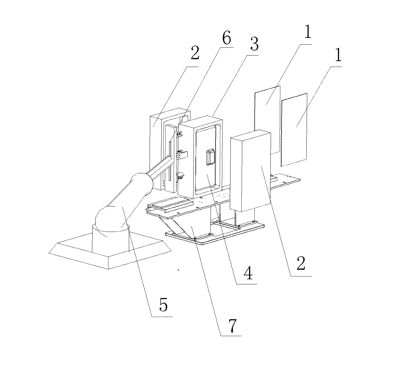
[0048]1) Blank two parisons 1, where the two parisons 1 after being blanked are separately located at an intermediate location between mold halves 2 of a two-piece mold and a pre-molding template 3, and for details, reference is made to FIG. 1.

[0049]2) Close the mold halves 2 of the mold and the pre-molding template 3, where reference is made to FIG. 2.

[0050]3) Pre-stretch the molten parisons by using auxiliary male molds 4 in the pre-molding template 3.

[0051]4) Perform internal high-pressure blow molding, and pre-mold two housing portions.

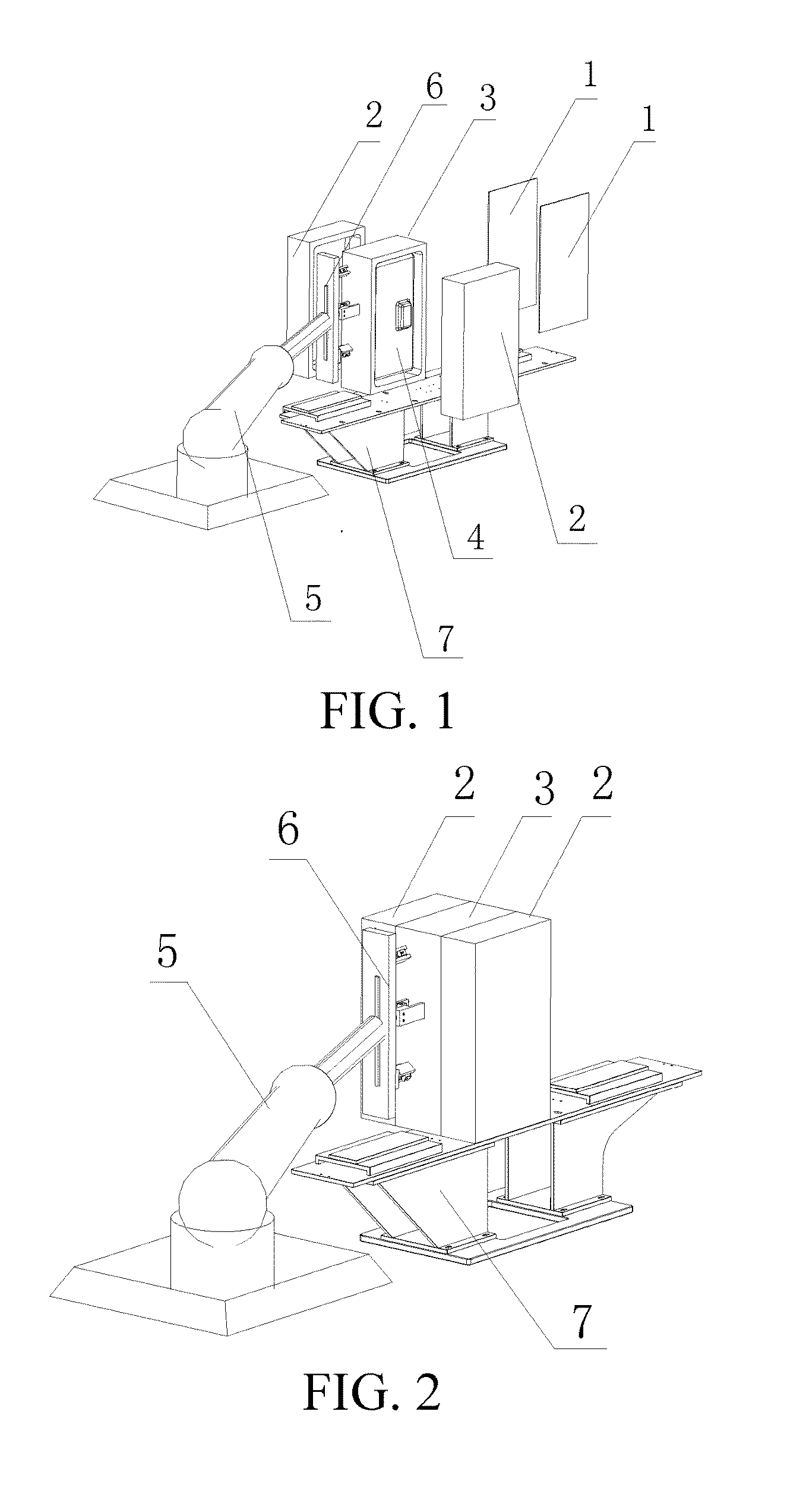
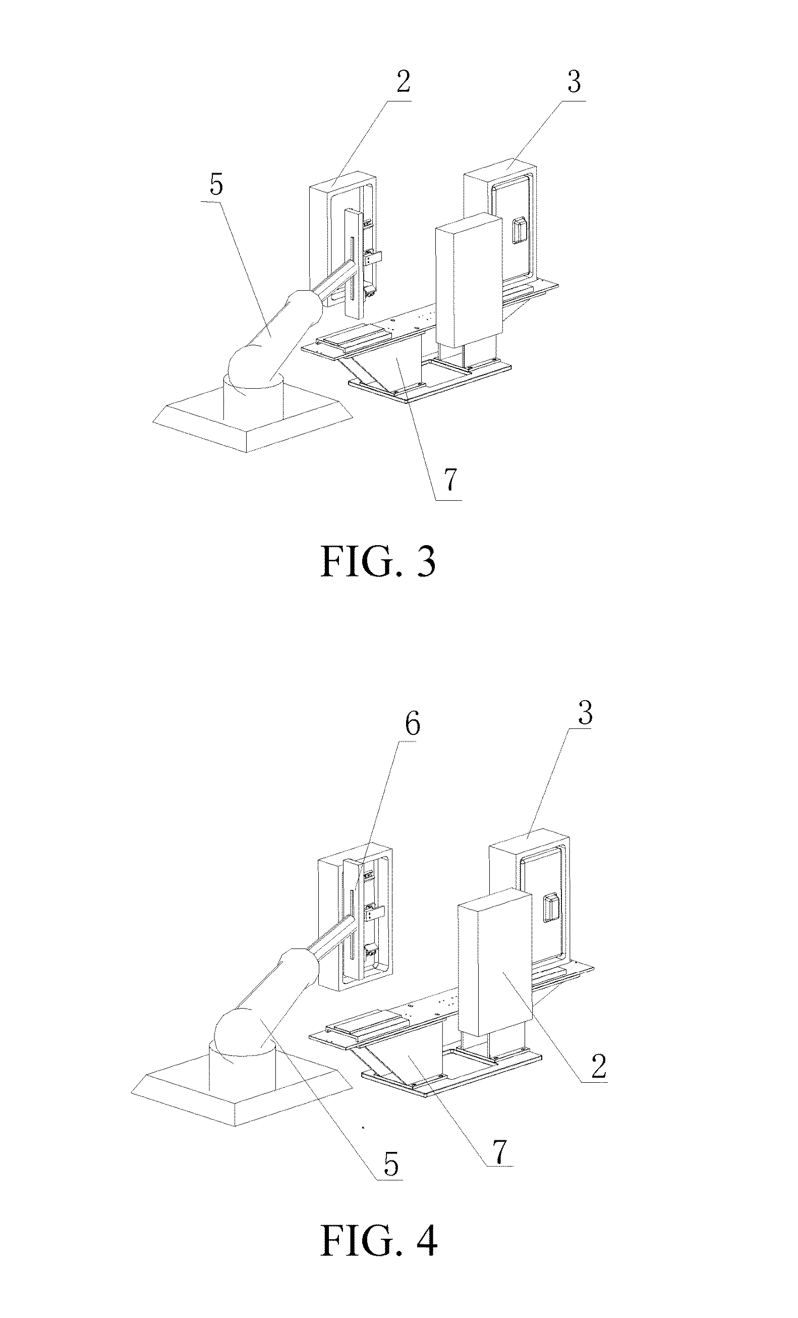
[0052]5) Open the mold halves 2 of the mold and withdraw the pre-molding template 3, where reference is made to FIG. 3.

[0053]6) Move in a component built-in mechanism 6 to perform built-in component connection, where reference is made to FIG. 4. After the pre-molding tem...

embodiment 2

[0055]Referring to FIG. 10, as an improvement of the present invention, the auxiliary male molds 4 on the pre-molding template in the step 3 are set as a split-type structure, and a specific step of the setting is as follows: 31) after the mold halves 2 of the mold and the pre-molding template 3 are closed, an actuating mechanism drives the auxiliary male molds 4 to move toward a direction of an inner wall of a mold cavity, so as to perform pre-stretching on the parisons, where the actuating mechanism includes an air cylinder, an oil cylinder or an electromotive mechanism. The actuating mechanism includes an air cylinder, an oil cylinder or an electromotive mechanism. The actuating mechanism drives the auxiliary male molds to move toward the direction of the inner wall of the mold cavity, and the molten parisons are pre-stretched under push of the auxiliary male molds, so as to perform pre-stretching on the parisons; the pre-stretching is performed on the parisons by using the auxil...

embodiment 3

[0056]Referring to FIG. 10, further, as an improvement of the present invention, the auxiliary male molds 4 in the pre-molding template 3 in the step 3 are set as a split-type structure, and a specific step of the setting is as follows: 31) after the mold halves 2 of the mold and the pre-molding template 3 are closed, the parisons are adsorbed in the mold in vacuum, and at the same time of the adsorption, an actuating mechanism drives the auxiliary male molds 4 to move toward a direction of an inner wall of a mold cavity, so as to perform pre-stretching on the parisons, where the actuating mechanism includes an air cylinder, an oil cylinder or an electromotive mechanism. The actuating mechanism drives the auxiliary male molds to move toward the direction of the inner wall of the mold cavity, and the molten parisons are pre-stretched under push of the auxiliary male molds 4, so as to perform pre-stretching on the parisons; the pre-stretching is performed on the parisons by using the ...


PUM

PropertyMeasurementUnit
Pressureaaaaaaaaaa

Abstract

A method for molding a two-piece blow molded hollow tank by using auxiliary male molds includes the following steps: 1) blanking two parisons; 2) closing mold halves of a mold and a pre-molding template; 3) pre-stretching the molten parisons by using auxiliary male molds in the pre-molding template; 4) performing internal high-pressure blow molding, and pre-molding two housing portions; 5) opening the mold, and withdrawing the pre-molding template; 6) moving in a component built-in mechanism to perform built-in component connection; 7) moving out the component built-in mechanism; 8) closing the mold for the second time and finally blow molding a hollow tank; and 9) opening the mold and taking out the product.

Description

BACKGROUND OF THE INVENTION[0001]1. Field of the Invention[0002]The present invention relates to a method for molding a blow molded hollow body, and in particular, to a method for molding a two-piece blow molded hollow body by using auxiliary male molds, and is particularly applicable to the field of manufacturing fuel tanks by blow molding.[0003]2. Related Art[0004]The HDPE 6-layer co-extrusion blow molding technology with an EVOH fuel barrier layer is currently a mainstream technology for manufacturing a plastic fuel tank. As environmental protection consciousnesses of governments around the world are enhanced, related policies and regulations make strict requirements on automobile main engine factories. For example, California in USA issued the PZEV, that is, Partial Zero Emission Vehicle regulations. As far as a plastic fuel tank produced by using the mainstream technology is concerned, the total evaporative emission of the plastic fuel tank includes evaporative emission of gaso...

Claims


Application Information

Patent Timeline
IPC IPC(8): B29C49/00B29C49/18
CPCB29C49/0047B29L2031/7172B29C49/18B29C49/04B29C49/20B29C49/4247B29C49/4252B29C2049/2008B29C2049/2073B29C2049/2082B29C49/02B29C49/28B29C2949/08B29C49/0691
Inventor SUN, YANJIANG, LINXU, SONGJUNLIU, LIANGGAO, DEJUNWANG, YEWU, LUSHUNLI, JIESU, WEIDONGWANG, CHANGRULI, XIAOJUNYANG, QUANZHOU
Owner YAPP AUTOMOTIVE PARTS
Why Eureka
Try Eureka