Light flux controlling member, light emitting device and illumination apparatus

a technology of light flux and control member, which is applied in the direction of lighting and heating apparatus, semiconductor devices for light sources, instruments, etc., can solve the problems of reducing the optical performance of the light emitting device, and achieve the effect of preventing a decrease in optical performance and high yield

Inactive Publication Date: 2015-11-05
ENPLAS CORP
View PDF3 Cites 7 Cited by
  • Summary
  • Abstract
  • Description
  • Claims
  • Application Information

AI Technical Summary

Benefits of technology

[0012]According to the present invention, it is possible to provide a light flux controlling member capable of preventing a decrease in the optical performance due to sticking of an adhesive when fixing the light flux controlling member to a substrate. Accordingly, according to the present invention, it is possible to provide a light emitting device and an illumination apparatus that can be manufactured at high yield without causing size increase.

Problems solved by technology

When the Fresnel lens is thus fixed using an adhesive, there is a risk that the adhesive undesirably sticks to an optical surface of the Fresnel lens and reduces the optical performance of the light emitting device.

Method used


Image

  • Light flux controlling member, light emitting device and illumination apparatus
  • Light flux controlling member, light emitting device and illumination apparatus
  • Light flux controlling member, light emitting device and illumination apparatus

Examples


embodiment 1

(Configurations of Light Flux Controlling Member and Light Emitting Device)

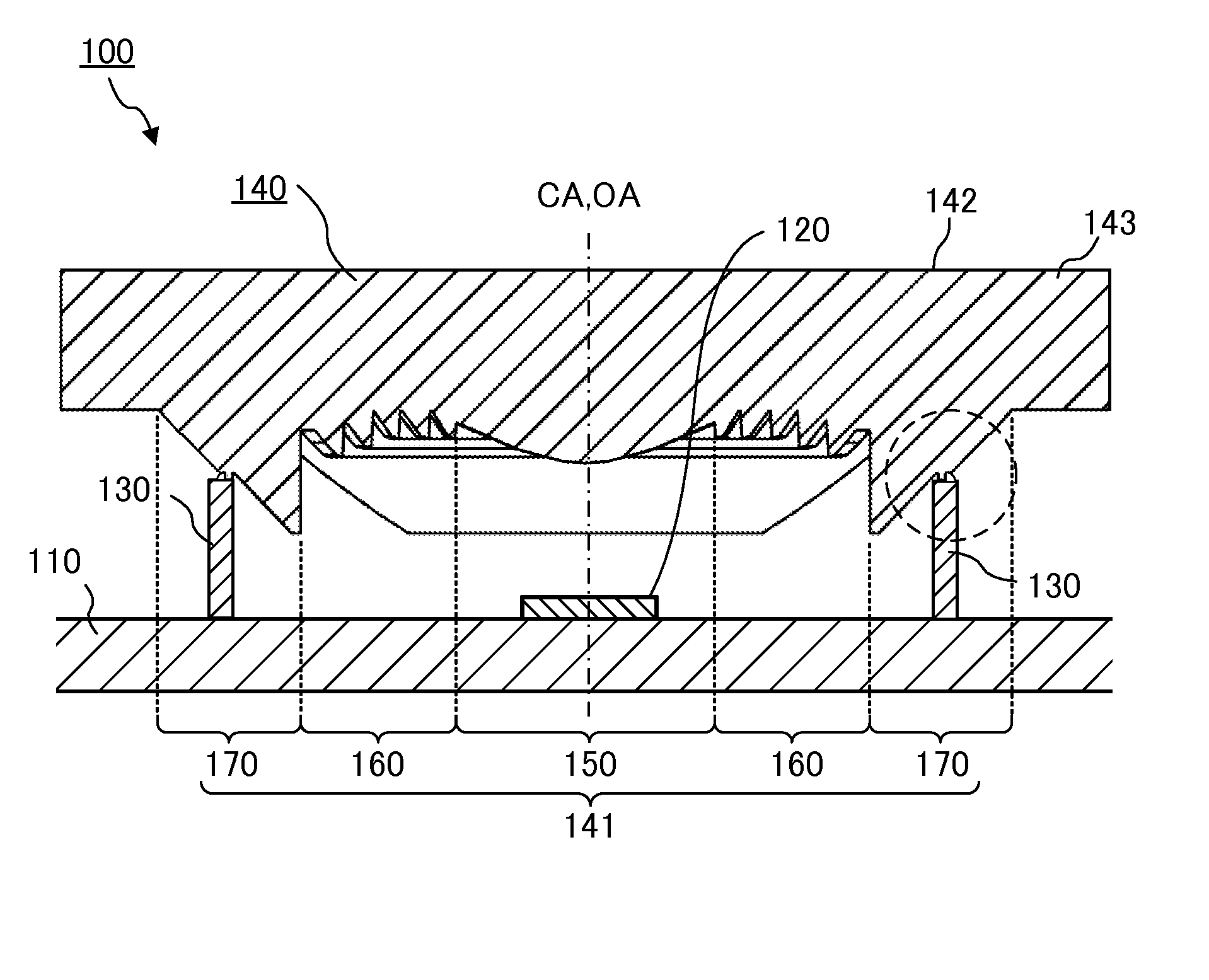
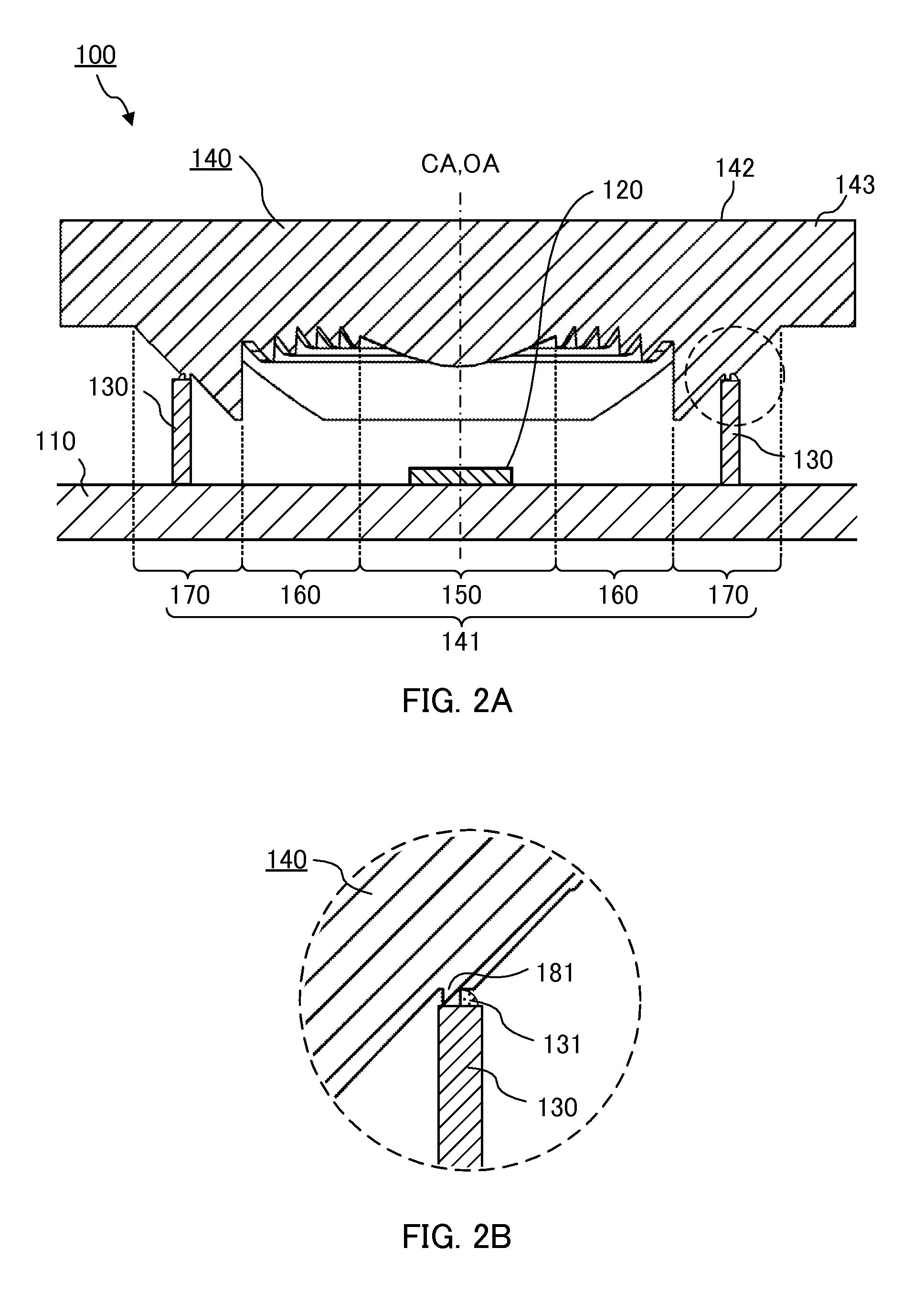
[0030]FIG. 2A is a sectional view of light emitting device 100 according to Embodiment 1 of the present invention. FIG. 2B is a partially enlarged sectional view of an area illustrated by a broken line in FIG. 2A. As illustrated in FIG. 2A, light emitting device 100 includes substrate 110, light emitting element 120, supporting part 130 and light flux controlling member 140.

[0031]Substrate 110 supports light emitting element 120 and light flux controlling member 140. The type of substrate 110 is not particularly limited. Substrate 110 is, for example, a glass composite substrate or a glass epoxy substrate.

[0032]Light emitting element 120 is a light source of light emitting device 100, and is fixed onto substrate 110. Light emitting element 120 is, for example, a light emitting diode (LED) such as a white light emitting diode.

[0033]Supporting part 130 is fixed onto substrate 110, and positions (supports) light...

embodiment 2

[0072]The light emitting device and the illumination apparatus according to Embodiment 2 differ, respectively, from light emitting device 100 and illumination apparatus 500 according to Embodiment 1 in the shape of light flux controlling member 240. Light flux controlling member 240 according to Embodiment 2 differs from light flux controlling member 140 according to Embodiment 1 only in the shape of stepped surface 278 in second reflection surface 274 of outermost lens part 270. Thus, the same components as those of light emitting device 100 and illumination apparatus 500 according to Embodiment 1 are indicated by the same reference signs, and the explanations therefor will be omitted. The components that are different from those of light flux controlling member 140 will be mainly described.

(Configurations of Light Flux Controlling Member and Light Emitting Device)

[0073]FIGS. 10, and 11A, 11B and 11C are drawings illustrating the configuration of light flux controlling member 240 a...

embodiment 3

(Configurations of Light Flux Controlling Member and Light Emitting Device)

[0078]The light emitting device and the illumination apparatus according to Embodiment 3 differ, respectively, from light emitting device 100 and illumination apparatus 500 according to Embodiment 1 in the shape of light flux controlling member 340. Light flux controlling member 340 according to Embodiment 3 differs from light flux controlling member 140 according to Embodiment 1 only in the shape of stepped surface 378 in second reflection surface 374 of outermost lens part 370. Thus, the same components as those of light emitting device 100 and illumination apparatus 500 according to Embodiment 1 are indicated by the same reference signs, and the explanations therefor will be omitted. The components that are different from those of light flux controlling member 140 will be mainly described.

[0079]FIGS. 12, and 13A, 13B and 13C are drawings illustrating the configuration of light flux controlling member 340 a...


PUM


Abstract

A light flux controlling member of the present invention includes an incidence area and an emission area. The incidence area includes a plurality of protrusions each having an incidence surface, a reflection surface, and a ridge line. The reflection surface disposed outermost includes a plurality of split reflection surfaces that reflects light having entered the light flux controlling member toward the emission area, and one or two or more stepped surfaces disposed between the two adjacent split reflection surfaces and at a dead angle position relative to a traveling direction of the light having entered the light flux controlling member. The protrusion disposed outermost has a projection part projecting in a direction along a central axis, with a tip portion thereof being closer to the emission area than an end portion of the light flux controlling member on a light emitting element side is in the direction along the central axis.

Description

CROSS REFERENCE TO RELATED APPLICATIONS [0001]This application is entitled to and claims the benefit of Japanese Patent Application No. 2014-095281, filed on May 2, 2014, the disclosure of which including the specification, drawings and abstract is incorporated herein by reference in its entirety.TECHNICAL FIELD [0002]The present invention relates to a light flux controlling member that controls the distribution of light emitted from a light emitting element, and a light emitting device and an illumination apparatus that have the light flux controlling member.BACKGROUND ART [0003]In recent years, from the viewpoint of energy conservation and miniaturization, illumination apparatuses using light emitting diodes (hereinafter also referred to as “LED”) as light sources, (LED flashes), have been used as light emitting devices for imaging cameras. As the light emitting devices described above, light emitting devices in which an LED and a Fresnel lens are combined are well known.[0004]Gen...

Claims


Application Information

Patent Timeline
Patent Type & Authority Applications(United States)
IPC IPC(8): F21V5/04F21V17/08F21V17/10F21V5/00F21V19/00
CPCF21V5/045F21V5/008F21V17/08F21V17/101F21V19/0035F21Y2115/10G02B3/08
Inventor SAITO, TOMOHIRO
Owner ENPLAS CORP
Why Eureka
Try Eureka