Distributed electric power generation system, control station, and method of controlling the same

a technology of electric power generation system and control station, applied in the direction of computer control, emergency power supply arrangement, instruments, etc., can solve problems such as running costs, and achieve the effect of reducing running costs and increasing efficiency

Active Publication Date: 2015-11-05
NEC CORP
View PDF2 Cites 23 Cited by
  • Summary
  • Abstract
  • Description
  • Claims
  • Application Information

AI Technical Summary

Benefits of technology

[0022]According to the embodiments of the present invention, there can be provided a distributed electric power generation system that can reduce a running cost through selective control of electric power generators to be ope...

Problems solved by technology

However, the inventor has found one problem in an aspect of a running cost upon operating a distributed elec...

Method used


Image

  • Distributed electric power generation system, control station, and method of controlling the same
  • Distributed electric power generation system, control station, and method of controlling the same
  • Distributed electric power generation system, control station, and method of controlling the same

Examples


embodiment 1

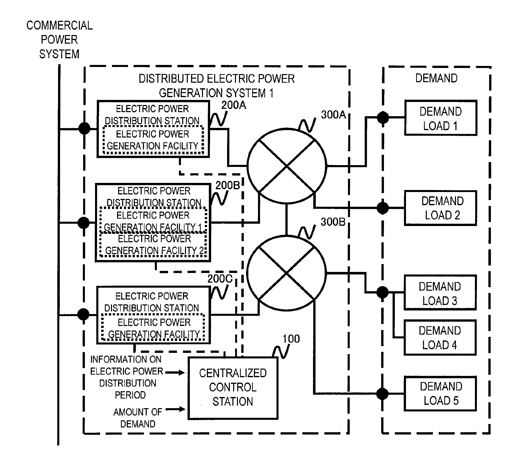
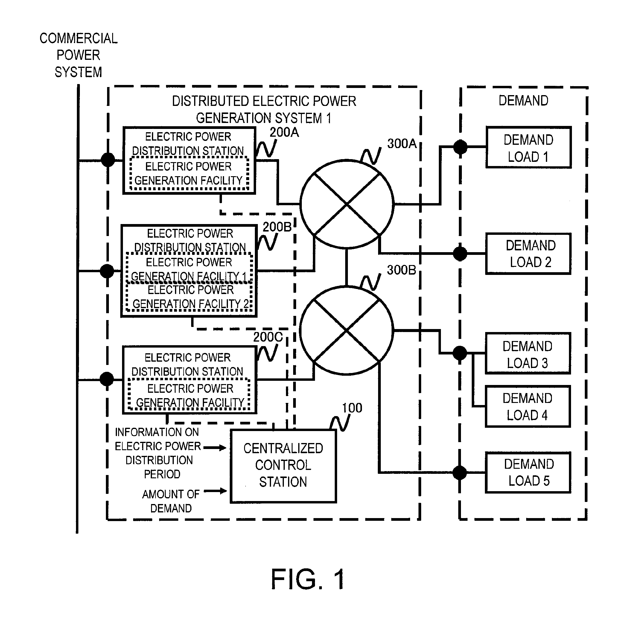
[0047]FIG. 1 is a system configuration diagram showing a distributed electric power generation system according to Embodiment 1.

[0048]The distributed electric power generation system 1 illustrated in FIG. 1 can supply electric power to a plurality of demands (demand loads) present in a predetermined grid (also referred to as a sector or a cell) from a plurality of electric power generation facilities along with a commercial power supply.

[0049]As illustrated, the distributed electric power generation system 1 includes a centralized control station 100, a plurality of electric power distribution stations 200 (200A-200C), and power transmission grid networks 300 (300A, 300B). The distributed electric power generation system 1 is connected to a commercial power system as an external power source and demand loads located at various places within a managed area. In FIG. 1, the demand loads 1, 2, . . . represent consumers who consume distributed electric power, such as houses, buildings, s...

embodiment 2

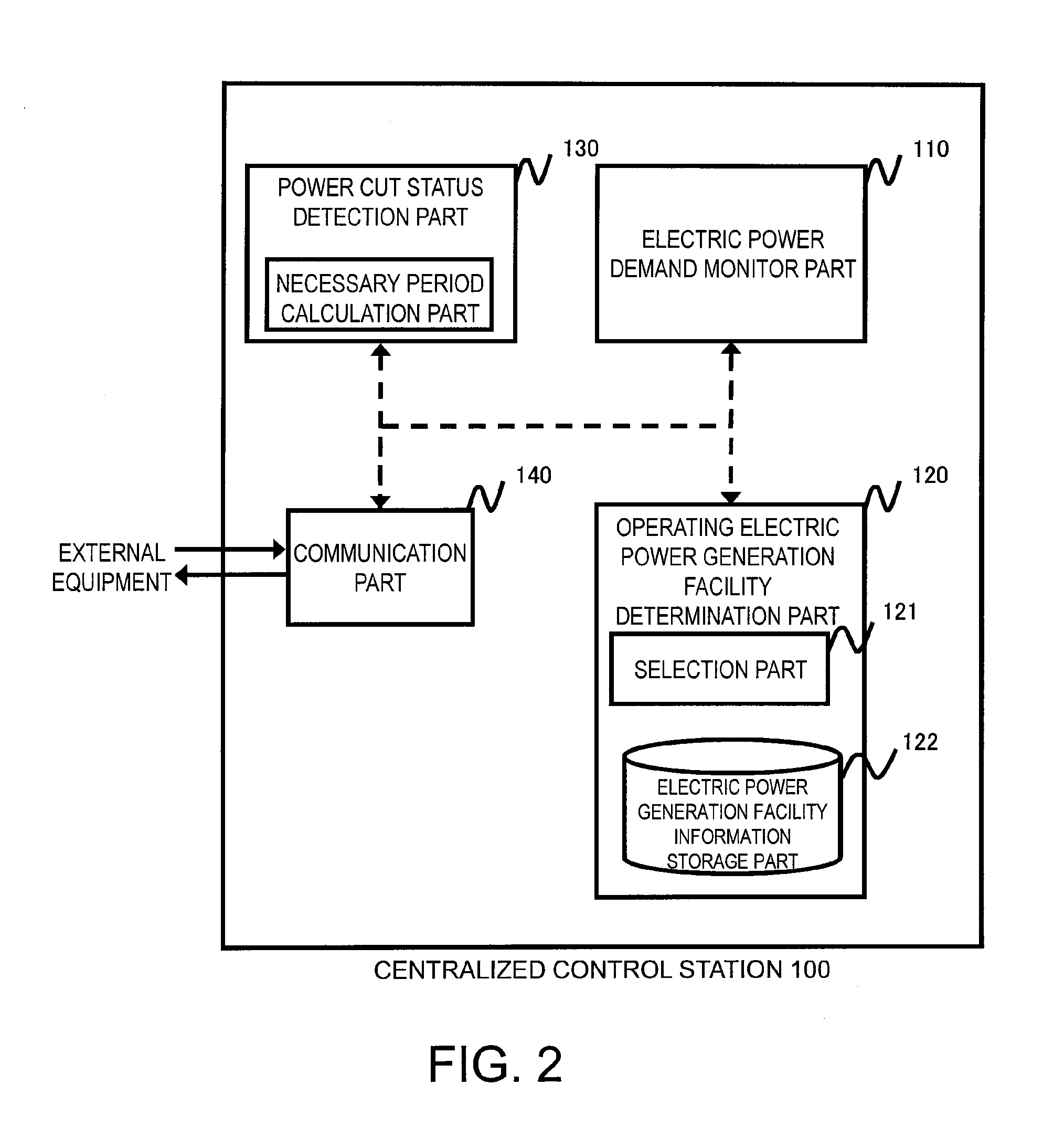
[0105]In the present embodiment, when a power cut is detected by the distributed electric power generation system, a plan to determine how to supply electric power to power loads connected in a usual state is determined in each of the electric power distribution stations. Therefore, a distributed control station including the aforementioned centralized control station 100 is provided in all or some of the electric power distribution stations 200.

[0106]The following determination process is performed by the selection part 121 of the operating electric power generation facility determination part 120.

[0107]FIG. 5 is a flow chart explanatory of an operation example of the operating electric power generation facility determination part 120 in a case where a power cut is detected in Embodiment 2.

[0108]The operating electric power generation facility determination part 120 detects a power cut (F301), then identifies an electric power demand (F302), identifies a predicted power cut period ...

embodiment 3

[0113]In the present embodiment, there will be described a method of detecting a power cut in a distributed electric power generation system and, when two or more electric power generation facilities are to be operated among three or more electric power generation facilities, switching power transmission grid networks into an operation mode that assumes individual single operations in each of the stations. When a plurality of electric power generation facilities are to be connected, a grid arrangement may be designed in which all of the loads are connected to a single large grid while the electric power generation facilities are operated in parallel. If the system includes, as an electric power generation facility, a rotation type power generator such as a diesel generator, it is difficult to perform a parallel operation while maintaining the phase or power factor in a satisfactory manner. Furthermore, if the types, the manufacturers, the capacities, and the like of the electric pow...


PUM


Abstract

A distributed electric power generation system is configured to include a plurality of electric power distribution stations operable to receive electric power from an external power source and generate electric power in a balanced manner, a power transmission grid network connected to the plurality of electric power distribution stations for supplying received electric power to a plurality of demand loads using electric power, and a control station operable to acquire information on an electric power distribution period used to calculate a period during which electric power supply is needed, acquire an amount of power supply demand to be supplied via the power transmission grid network during the period during which electric power supply is needed, the period being determined from the acquired information on the electric power distribution period, and select one or a required number of electric power generation facilities for supplying electric power to the plurality of demand loads at a low cost based upon a start and stop cost and a running cost of each of the electric power distribution stations in accordance with the calculated electric power distribution period and the amount of power supply demand.

Description

TECHNICAL FIELD[0001]The present invention relates to a distributed electric power generation system connected with a power transmission grid network, and more particularly to a distributed electric power generation system and a control station that perform operation control of each of electric power generation means so as to optimize a running cost, and a method of controlling the same.BACKGROUND OF THE INVENTION[0002]Some distributed electric power supply systems have been proposed in which a plurality of electric power generation facilities are connected to demand loads via a power transmission grid network such that operation control of each of the electric power generation facilities can be performed.[0003]Proposed examples of distributed power supply systems include Patent Literatures 1 to 3.[0004]A distributed electric power supply system disclosed in Patent Literature 1 has a plurality of electric power generating apparatuses that supply electric power to power loads and an ...

Claims


Application Information

Patent Timeline
IPC IPC(8): H02J3/00G05B15/02
CPCG05B15/02H02J3/00H02J3/46H02J9/08H02J3/381Y04S10/12Y04S20/12H02J3/388H02J2300/10Y02B90/20Y02E40/70H02J13/00034H02J13/00002Y02E60/00Y04S10/30
Inventor TANI, YUMI
Owner NEC CORP
Why Eureka
Try Eureka