Aluminum alloy welding wire

a technology of aluminum alloy and welding wire, which is applied in the direction of welding/cutting media/materials, welding apparatus, manufacturing tools, etc., can solve the problems of affecting the mechanical properties achieved either by cold working or heat treatment, affecting the mechanical properties of welding wire, and affecting the selection of brazing and welding materials

Active Publication Date: 2015-11-12
ILLINOIS TOOL WORKS INC
View PDF2 Cites 11 Cited by
  • Summary
  • Abstract
  • Description
  • Claims
  • Application Information

AI Technical Summary

Problems solved by technology

Unlike steels and other metals, aluminum alloys present unique problems owing, for example, to their metallurgy, their melting points, the changes in strength as a function of particular alloying agents, and so forth.
Moreover, increasing interest in both thinner aluminum alloy workpieces on one hand, and thicker workpieces on the other presents additional difficulties in the selection of brazing and welding materials that perform well and provide the desired physical and mechanical properties.
The temperatures used in brazing may anneal both non-heat treatable and heat treatable aluminum alloys, which may alter the mechanical properties achieved either by cold working or heat treatment and aging operations.
Therefore, brazing, while quite useful in many applications, may not be suitable to join high strength structural alloys.
Currently available aluminum alloy brazing and welding wires do not, however, satisfy the needs of many modern applications.
For example, current products do not offer the desired fluidity during the joining operation, or the desired strength when combined with base material in welding applications, particularly when used with a range of modern welding processes.
Moreover, where welding arcs vary in penetration, heat, weld pool formation, and so forth, current aluminum alloy wires and compositions do not provide a desired degree of consistency in terms of the composition and strength of the ultimate joint.

Method used


Image

  • Aluminum alloy welding wire

Examples


Embodiment Construction

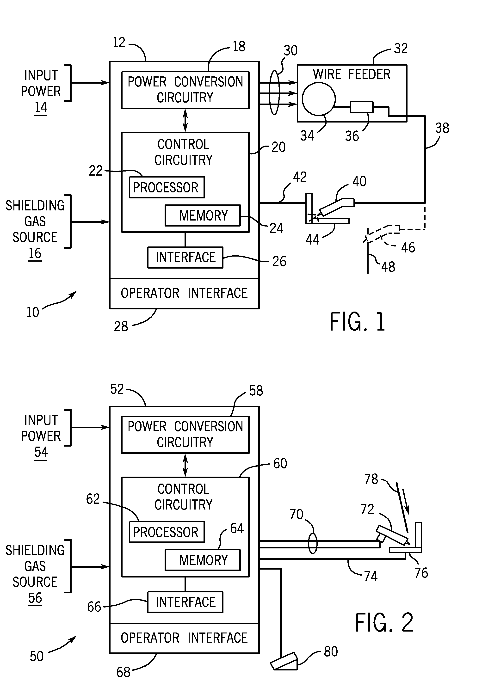
[0014]Presently disclosed embodiments include aluminum alloy compositions that are useful for metal bonding applications. Throughout the discussion, it should be borne in mind that these compositions are not necessarily limited to use in welding, or even as filler metals, but may be useful in other applications and operations, such as brazing or other types of metal bonding. Similarly, references made to “welding wire” should be understood as referring to any suitable form of adder metal, including without limitation, continuous wire intended for wire feeder applications (e.g., for metal inert gas (MIG) welding), rod and sticks (e.g., for tungsten inert gas (TIG) and stick welding), as well as other forms for welding, fusing, brazing, braze cladding of sheet and similar operations. It may be noted that the compositions of the disclosed alloys may be described in terms of weight percentages (wt %) of the individual components relative to the weight of the alloy. It may also be noted ...


PUM

PropertyMeasurementUnit
weight percentaaaaaaaaaa

Abstract

The present disclosure relates generally to the field of welding filler metals, and more particularly to compositions suitable for welding or brazing aluminum alloys. In an embodiment, an aluminum-silicon-magnesium alloy, includes a magnesium content between approximately 0.1 wt % and approximately 0.5 wt %, wherein substantially all of the magnesium content is present as magnesium silicide. The alloy includes a silicon content between approximately 5.0 wt % and approximately 6.0 wt %, wherein at least 4.75 wt % of the silicon content is present as free silicon. The alloy includes one or more of iron, copper, manganese, zinc, and titanium. The alloy further includes a remainder of aluminum and trace components.

Description

CROSS REFERENCE TO RELATED APPLICATIONS[0001]This application is a Continuation-in-Part Application of U.S. patent application Ser. No. 14 / 161,432, entitled “Aluminum Alloy Welding Wire”, filed Jan. 22, 2014, which is a Continuation-in-Part Application of U.S. patent application Ser. No. 13 / 023,158, entitled “Aluminum Alloy Welding Wire”, filed Feb. 8, 2011, which is a Non-Provisional application of U.S. Provisional Patent Application No. 61 / 303,149, entitled “Aluminum Alloy Welding Wire”, filed Feb. 10, 2010, all of which are herein incorporated by reference in their entireties for all purposes.BACKGROUND[0002]The present disclosure relates generally to the field of welding filler metals, and more particularly to compositions suitable for welding or brazing aluminum alloys.[0003]Many different processes are known and currently in use for joining metal articles, including brazing and welding. Both such operations may be used for joining of aluminum and aluminum alloy articles. Unlik...

Claims


Application Information

Patent Timeline
Patent Type & Authority Applications(United States)
IPC IPC(8): B23K35/28C22C21/00
CPCC22C21/00B23K35/288B23K35/0261B23K35/28B23K35/286B23K35/383B23K35/40C22C21/02
Inventor ANDERSON, BRUCE EDWARDBERUBE, PATRICK
Owner ILLINOIS TOOL WORKS INC
Why Eureka
Try Eureka