Method of preparing a mould for vacuum resin transfer moulding

Inactive Publication Date: 2015-11-12
SIEMENS AG
View PDF0 Cites 7 Cited by
  • Summary
  • Abstract
  • Description
  • Claims
  • Application Information

AI Technical Summary

Benefits of technology

[0032]By the use of the above-described method of preparing a mould for wind turbine blades or for generating a new vacuum flow topology in a mould for wind turbine blades, or by the use of a peel ply layer for generating a vacuum flow topology at a surface of a mould for wind turbine blades, it is advantageous to use peel ply layers comprising peel plies with two or more intersecting sets of threads. The fabric pattern with these threads enforces vacuum flow along the direction of the threads during the application of vacuum in the wind turbine bald moulding process. In exemplified peel plies the threads are arranged in two intersecting sets of threads. Advantageously, the threads are arranged at an angel of about 80 to 100 degrees, more specifically the two set of threads are crossing each other nearly at an perpendicular angle (perpendicular means in this regard about 90 degrees±5 degrees).
[0033]The texture pattern results in a very even pattern transferred to the mould surface. Generally, the weave of the fabric determines how “fine” the pattern is. In other words, the pattern has a light or faint patterned structure. More particularly, the roughness of the surface depends on the filament structure and thickness of the peel plies used. The skilled person knows which peel ply may be favourable for the vacuum flow topology of the mould to be prepared depending on the device to be moulded. The skilled person can then select the desired peel ply layers freely available on the market.
[0034]Due to this specific vacuum flow topology of the mould surface prepared by the methods and uses of the present invention, a mould with this specific surface topology would require a structure with a smaller roughness than a mould using a traditional release agent for de-moulding. With the vacuum flow topology prepared according to the invention, when the vacuum is cut, the casting, for example of a wind turbine blade, is only held in place by gravity. The force of de-moulding is almost non-existent. Therefore, with this new mould surface topology, the de-moulding process is easier even if no release a

Problems solved by technology

However, it is not easy to apply the release agent so that these requirements are met, and the result can be an uneven or dimpled component surface.
However, when casting on a vacuum film, it is necessary to hold t

Method used


Image

  • Method of preparing a mould for vacuum resin transfer moulding

Examples


Embodiment Construction

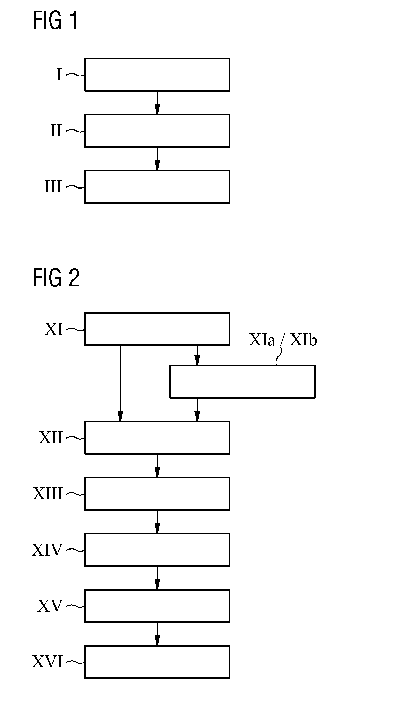
[0040]FIG. 1 shows a block diagram describing the steps used for preparing a mould according to the invention during the manufacturing process of a mould. The method of preparing a mould having a moulding cavity surface with vacuum flow topology for vacuum resin transfer moulding starts with step I in which a number of peel ply layers are pressed into an uncured resin layer of a mould just prepared. The peel ply layers are pressed into the uncured resin surface for building up the moulding cavity surface, more specifically for generating the specific pattern in the resin when cured.

[0041]In the next step, step II, the resin of the resin layer is cured so that the internal resin structure is hardened.

[0042]Thereafter, the peel ply layers are detached in step III to generate the vacuum flow topology in the moulding cavity surface. More specifically, the topology is a negative of the texture of the peel ply. The roughness of the structure highly depends on the used peel ply filaments a...


PUM

PropertyMeasurementUnit
Angleaaaaaaaaaa
Flow rateaaaaaaaaaa

Abstract

A method of preparing a mould having a moulding cavity surface with vacuum flow topology for vacuum resin transfer moulding is provided. This method includes: pressing a number of peel ply layers into an uncured resin layer for building up the moulding cavity surface, curing the resin of the resin layer, and detaching the peel ply layers to generate the vacuum flow topology in the moulding cavity surface. A mould for wind turbine blades having a vacuum flow topology prepared by such a method is also provided.

Description

CROSS REFERENCE TO RELATED APPLICATIONS[0001]This application claims the benefit of European Application No. EP14167337 filed May 7, 2014, incorporated by reference herein in its entirety.FIELD OF INVENTION[0002]The invention describes a method of preparing a mould for vacuum resin transfer moulding and its use, use of a peel ply layer for generating a vacuum flow topology at a surface of a mould, and a mould for wind turbine blades.BACKGROUND OF INVENTION[0003]Wind turbine rotor blades conventionally are manufactured using a technique such as the closed-mould casting technique in which the entire blade can be moulded. Glass fibre matting is used to build up component layers in a suitably shaped mould, and the layers of matting are bonded with a resin and cured in the mould to give a fibre-reinforced polymer or glass-reinforced plastic, generally referred to simply as ‘fibreglass’.[0004]To facilitate releasing the finished fibreglass component after curing, the mould is usually coat...

Claims


Application Information

Patent Timeline
IPC IPC(8): B29C33/42
CPCB29L2031/757B29C33/42B29C33/3842B29C33/3857B29L2031/085Y02P70/50
Inventor STEGE, JASON
Owner SIEMENS AG
Why Eureka
Try Eureka