
Method for turbine wheel balance stock removal

a technology of turbine wheels and shaftandwheels, which is applied in the direction of liquid fuel engines, vessel construction, marine propulsion, etc., can solve the problems of turbine wheel b>100/b> being expensive, fatigue failure of the turbine wheel, and high degree of non-recoverable cos

Inactive Publication Date: 2015-11-12
BORGWARNER INC
View PDF5 Cites 12 Cited by
  • Summary
  • Abstract
  • Description
  • Claims
  • Application Information

AI Technical Summary

Benefits of technology

The invention is related to a new design for a turbine wheel used in turbochargers. The design includes a hub with a back-wall that has a scallop in its edge. The scallop is a multi-pass or single-pass design that removes material from the back-wall in a way that requires multiple or single passes of a cutting tool. This asymmetrical design helps to balance the turbine wheel and improve its performance. The technical effect of this invention is to improve the stability and efficiency of turbochargers by optimizing the design of the turbine wheel.

Problems solved by technology

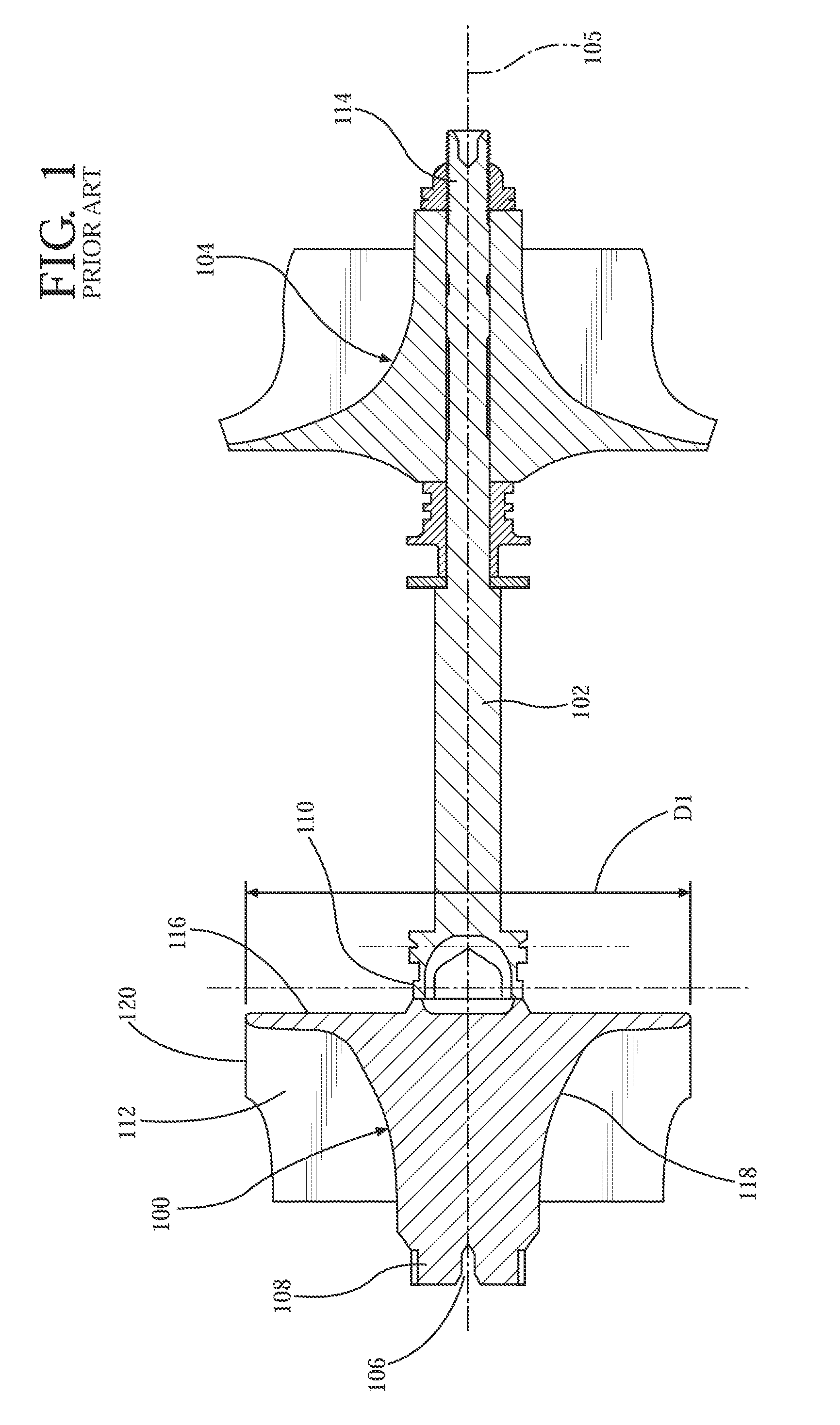
The turbine wheel 100 is expensive because it is typically cast from a nickel based superalloy with over seventy percent (70%) by weight in nickel.
However, the rotational balance of the turbine wheel 100 is unknown until it is part of a finished shaft-and-wheel assembly, and unfortunately, the balancing step is generally the last operation in the manufacture of the shaft-and-wheel assembly.
Thus, if the shaft-and-wheel assembly is scrapped due to balance problems, a high degree of non-recoverable cost has already been expended.
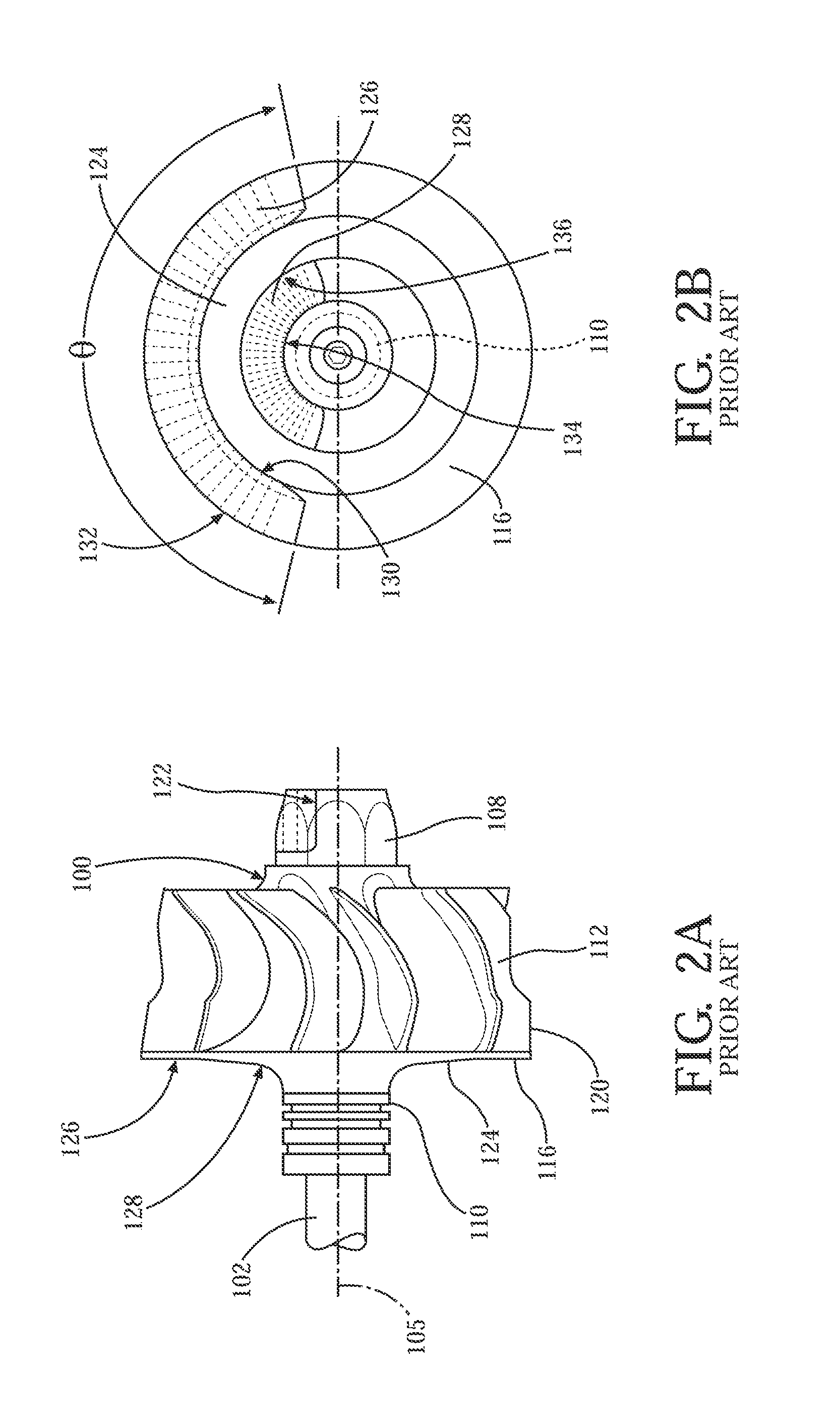
As a result, removing material from the surface 124 of the back-wall 116 may introduce stress risers in the remaining material which have the potential to cause fatigue failures in the turbine wheel 100.

Method used


Image

  • Method for turbine wheel balance stock removal
  • Method for turbine wheel balance stock removal
  • Method for turbine wheel balance stock removal

Examples


first embodiment

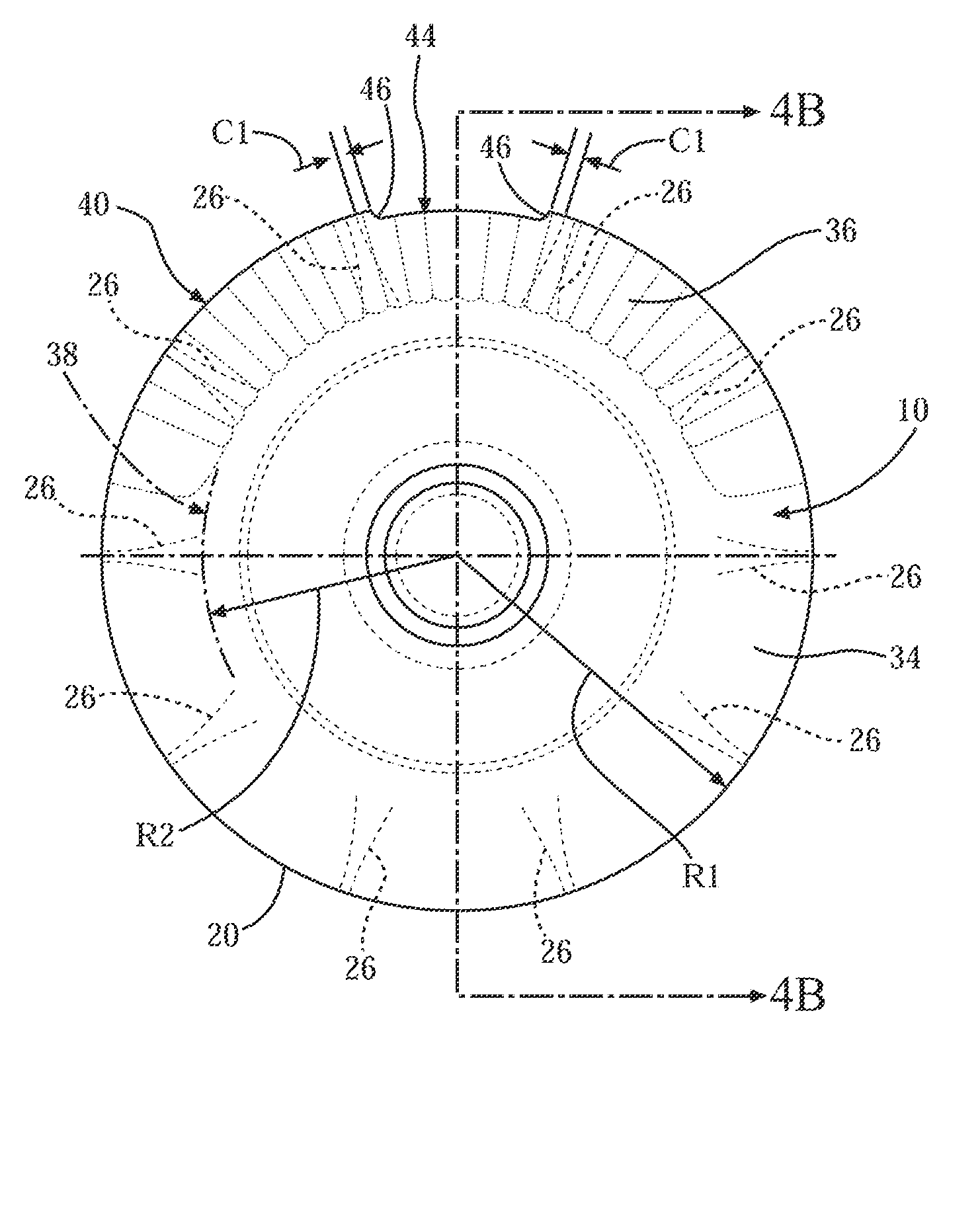
[0033]In the invention, a multi-pass or pattern scallop is shown generally at 44 in FIGS. 4A through 4C. The multi-pass scallop 44 is elongated in the circumferential direction such that material is removed from the back-wall 22 over a designated angle, which requires multiple passes with a cutting tool. A maximum angle for each multi-pass scallop 44 is defined between two turbine blades 26 that are adjacent such that there is a first distance C1 between an end 46 of the multi-pass scallop 44 and a fillet radius where the turbine blade 26 intersects the deck face 42 of the hub 12. Each multi-pass scallop 44 can extend in the circumferential direction over any angle up to the maximum angle without varying from the scope of the invention. The first distance C1 between the end 46 of the multi-pass scallop 44 and the fillet radius of the turbine blade 26 is at least approximately 0.5 millimeters. It is appreciated that the back-wall 22 is subject to high stress conditions near the turbi...

second embodiment

[0034]In the invention, a single-pass scallop is shown generally at 48 in FIGS. 5A through 5C. The single-pass scallop 48 is generally semi-circular such that material is removed from the back-wall 22 with a single pass of a cutting tool. There is a second distance C2 between a side 50 of the single-pass scallop 48 and the fillet radius where the turbine blade 26 intersects the deck face 42 of the hub 12. The second distance C2 between the side 50 of the single-pass scallop 48 and the fillet radius of the turbine blade 26 is at least approximately 0.5 millimeters. Also, when there is more than one single-pass scallop 48 between two turbine blades 26 that are adjacent, there is a third distance C3 between the sides 50 of the single-pass scallops 48 that are adjacent. The third distance C3 between the sides 50 of the single-pass scallops 48 that are adjacent is at least approximately 2.0 millimeters. The third distance C3 is selected to avoid a localized high stress area in the back-w...


PUM

PropertyMeasurementUnit
distanceaaaaaaaaaa
distanceaaaaaaaaaa
angleaaaaaaaaaa

Abstract

A turbine wheel (10) for a turbocharger includes a hub (12) extending in an axial direction between a nose (14) and a back-wall (22). The hub (12) defines an axis of rotation (28) extending in the axial direction and the back-wall (22) includes a peripheral edge (20). A plurality of turbine blades (26) is coupled to the hub (12) and is disposed in a circumferential direction generally at equal intervals around the axis of rotation (28). At least one scallop (44, 48) is formed in the peripheral edge (20) of the back-wall (22) for balancing the turbine wheel (10). The at least one scallop (44, 48) is positioned along the peripheral edge (20) such that the peripheral edge (20) is not symmetrical in the circumferential direction about the axis of rotation (28).

Description

CROSS-REFERENCE TO RELATED APPLICATIONS[0001]This application claims priority to and all the benefits of U.S. Provisional Application No. 61 / 667,174, filed on Jul. 2, 2012, and entitled “Method For Turbine Wheel Balance Stock Removal.”BACKGROUND OF THE INVENTION[0002]1. Field of the Invention[0003]The present invention relates to a method for balancing a shaft-and-wheel assembly of a turbocharger. More particularly, the present invention relates to a method of removing balance stock from a turbine wheel having a “fullback” back-wall.[0004]2. Description of Related Art[0005]A turbocharger is a type of forced induction system used with internal combustion engines. Turbochargers deliver compressed air to an engine intake, allowing more fuel to be combusted, thus boosting an engine's horsepower without significantly increasing engine weight. Thus, turbochargers permit the use of smaller engines that develop the same amount of horsepower as larger, normally aspirated engines. Using a sma...

Claims


Application Information

Patent Timeline
Patent Type & Authority Applications(United States)
IPC IPC(8): F01D5/02F02C6/12
CPCF01D5/027Y10T29/4932F02C6/12F02B39/16
Inventor TAKABATAKE, LAUROPAULINO, REINALDO
Owner BORGWARNER INC
Learn More