Eureka AIR delivers breakthrough ideas for toughest innovation challenges, trusted by R&D personnel around the world.

Temperature Compensated Transmission Line Based Liquid Level Sensing Apparatus and Method

Active Publication Date: 2015-11-12
GUNSAY METIN A
View PDF6 Cites 6 Cited by
  • Summary
  • Abstract
  • Description
  • Claims
  • Application Information

AI Technical Summary

Benefits of technology

The present invention provides an improved liquid level sensor that is more cost-effective, easy to use and calibrate, and provides reliable data. The sensor uses a temperature compensated peak detector circuit as an AM demodulator to reduce the cost of the sensor electronics. Additionally, the sensor uses arbitrarily long transmission lines to increase the fluid measurement range. The sensor probe is also more cost-effective, using off the shelf transmission line cable. Furthermore, the sensor easily changes and replaces worn transmission line sensing elements, and can be recalibrated for different lengths of transmission line.

Problems solved by technology

The problem with these types of measuring devices is that they are mechanical and have moving parts which may break or deteriorate over time and with use, are bulky and such devices which measure a continuum of levels are often very expensive.
Resistive sensors (see, U.S. Pat. No. 4,137,527; U.S. Pat. No. 4,276,454; U.S. Pat. No. 7,992,437; U.S. Pat. No. 5,719,556; U.S. Pat. No. 3,916,213), which consist of conductive probes inserted into a conductive liquid are often used, but they suffer from corrosion and can cause electrolysis when used in water.
The disadvantage of this type of sensor is that large plates are difficult and expensive to produce so measuring large ranges of water level becomes prohibitively expensive.
While the length of the sensor is unbounded, the electronics employed to measure the time delay of reflected pulses is often prohibitively expensive.

Method used


Image

  • Temperature Compensated Transmission Line Based Liquid Level Sensing Apparatus and Method
  • Temperature Compensated Transmission Line Based Liquid Level Sensing Apparatus and Method

Examples


Embodiment Construction

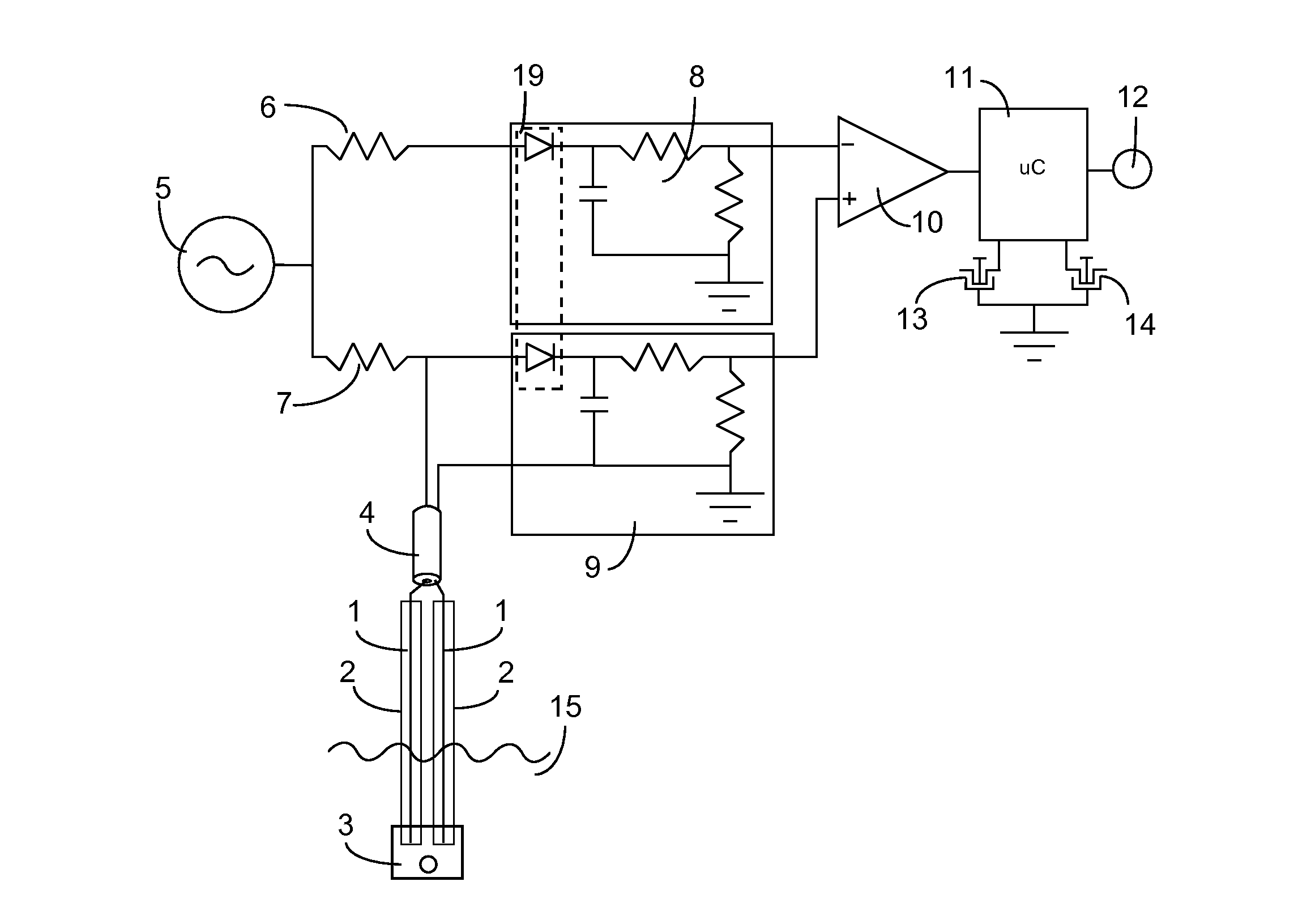
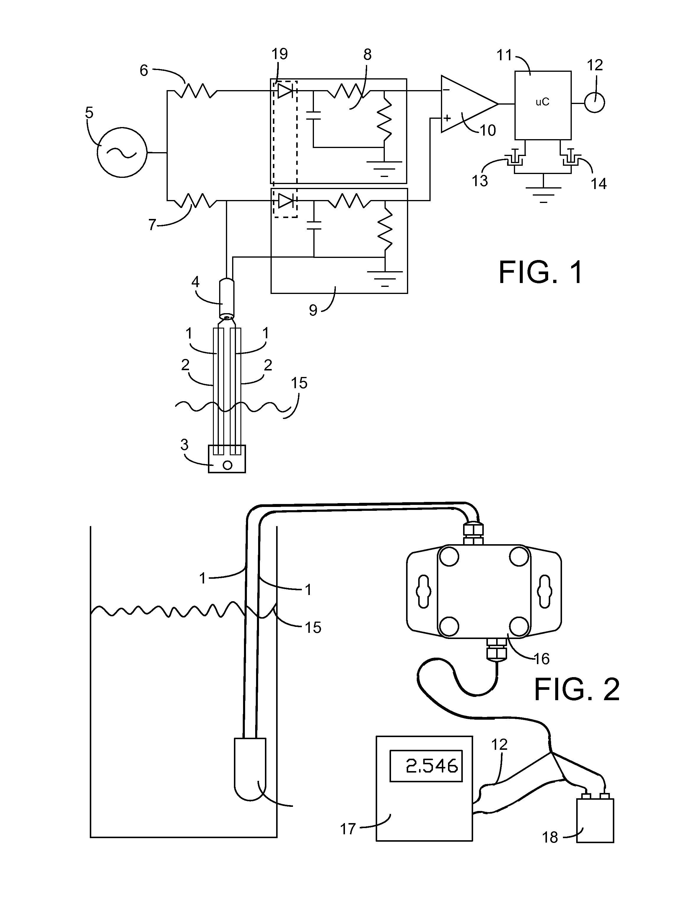
[0041]A block diagram of the preferred embodiment is shown in FIG. 1. A periodic function generator 5 provides a carrier frequency through a resistive or complex impedance network 7 to a transmission line probe 1 of one or more segments, which is partially submerged in a target liquid 15. The complex impedance network 7 with the transmission line 4, form a voltage divider whose output voltage magnitude is related to the impedance of the transmission line probe 1. The magnitude of the voltage divided signal will vary according to the dielectric constant of the liquid and the level of liquid surrounding the partially submersed transmission line probe. The output of this voltage divider is fed to an AM (Amplitude Modulated) demodulator, typically a peak detector 9, for the purpose of removing the carrier, and rendering a voltage which is related to the level of liquid surrounding the transmission line probe. One skilled in the art of electronics will recognize that any AM demodulation ...


PUM


Abstract

A sensor having a transmission line acting as a probe and an electronic circuit measures liquid levels. The sensor circuit uses a periodic signal generator to produce a carrier wave, which stimulates the transmission line, through a complex network coupling element. The complex impedance network forms a voltage divider with the transmission line, wherein the output of the voltage divider, is demodulated with an AM demodulator, such as a thermally compensated peak detector. This demodulated signal is related to the dielectric constant, and thus the liquid level of the material surrounding the partially submerged transmission line probe. The liquid level and the demodulated signal may be offset, scaled and linearized with a microcontroller containing signal processing routines, linearizing equations, stored calibration constants and look up tables.

Description

CROSS-REFERENCES TO RELATED APPLICATIONS[0001]This application claims priority as a non-provisional perfection of prior filed application No. 61 / 991,994, filed May 12, 2014, and incorporates the same by reference herein in its entirety.FIELD OF INVENTION[0002]This invention generally relates to liquid level sensing, and in particular to an apparatus used to measure the level of liquid in a systemBACKGROUND OF THE INVENTION[0003]The sensing and measuring of liquid levels is essential in many applications. For example, and without limitation, many water reservoirs need water level to be monitored so that they can be refilled, or to prevent overflow and flooding. Also, environmental sensing of water level in rivers, oceans, and lakes is becoming increasingly more important with climate change, and as demand for water resources increases.[0004]Many methods and devices for measuring liquid levels have been used. The most common is the mechanical float, which consists of buoyant floats co...

Claims


Application Information

Patent Timeline
IPC IPC(8): G01F23/26
CPCG01F23/266G01F23/26
Inventor GUNSAY, METIN A.
Owner GUNSAY METIN A
Why Eureka
Eureka Blog
Learn More