Induction heating coil and method for manufacturing induction heating coil

a technology of induction heating coil and manufacturing method, which is applied in the direction of manufacturing tools, induction current sources, electric/magnetic/electromagnetic heating, etc., can solve the problems of difficult to make the coil section from a single member, difficulty in achieving proficient skill, and complicated shape of the coil section, so as to reduce the imbalance of heat stress, increase the efficiency of producing and facilitate the production of the induction heating coil

Active Publication Date: 2015-11-12
KOYO THERMO SYST CO LTD
View PDF4 Cites 7 Cited by
  • Summary
  • Abstract
  • Description
  • Claims
  • Application Information

AI Technical Summary

Benefits of technology

[0037]According to this configuration, no brazed section needs to be provided either on the coil section itself or between the power supply section and the coil section. Accordingly, heat strain that is caused by a brazing operation does not occur between the power supply section and the heating coil section. Therefore, no special jig for lowering such heat strain is needed, making it possible to produce the induction heating coil more easily. Furthermore, since an operation for setting the above-described jig for brazing is not needed, it is possible to ra...

Problems solved by technology

Accordingly, the coil section has a complicated shape, and it is difficult to make the coil section from a single member.
In order to perform a brazing operation with accuracy, however, proficient skill is needed.
As a result, it is difficult to keep the brazing accuracy constant for each induction heating coil, and also difficult to make the induction heating coils in mass production with them formed in same (uniform) dimensions or shapes each other.
Furthermore, when the plurality of members constituting the coil section are brazed to each other, and when the coil section and the power supply section are brazed to each other, the brazing temperature is high, and thus heat strain inevitably occurs between the plurality of members constituting the coil section and between the coil section and the power supply section.
Furt...

Method used


Image

  • Induction heating coil and method for manufacturing induction heating coil
  • Induction heating coil and method for manufacturing induction heating coil
  • Induction heating coil and method for manufacturing induction heating coil

Examples


first embodiment

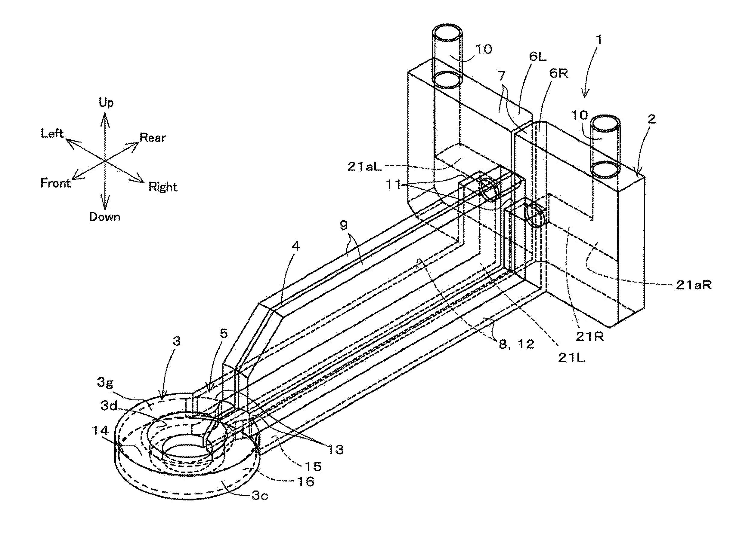
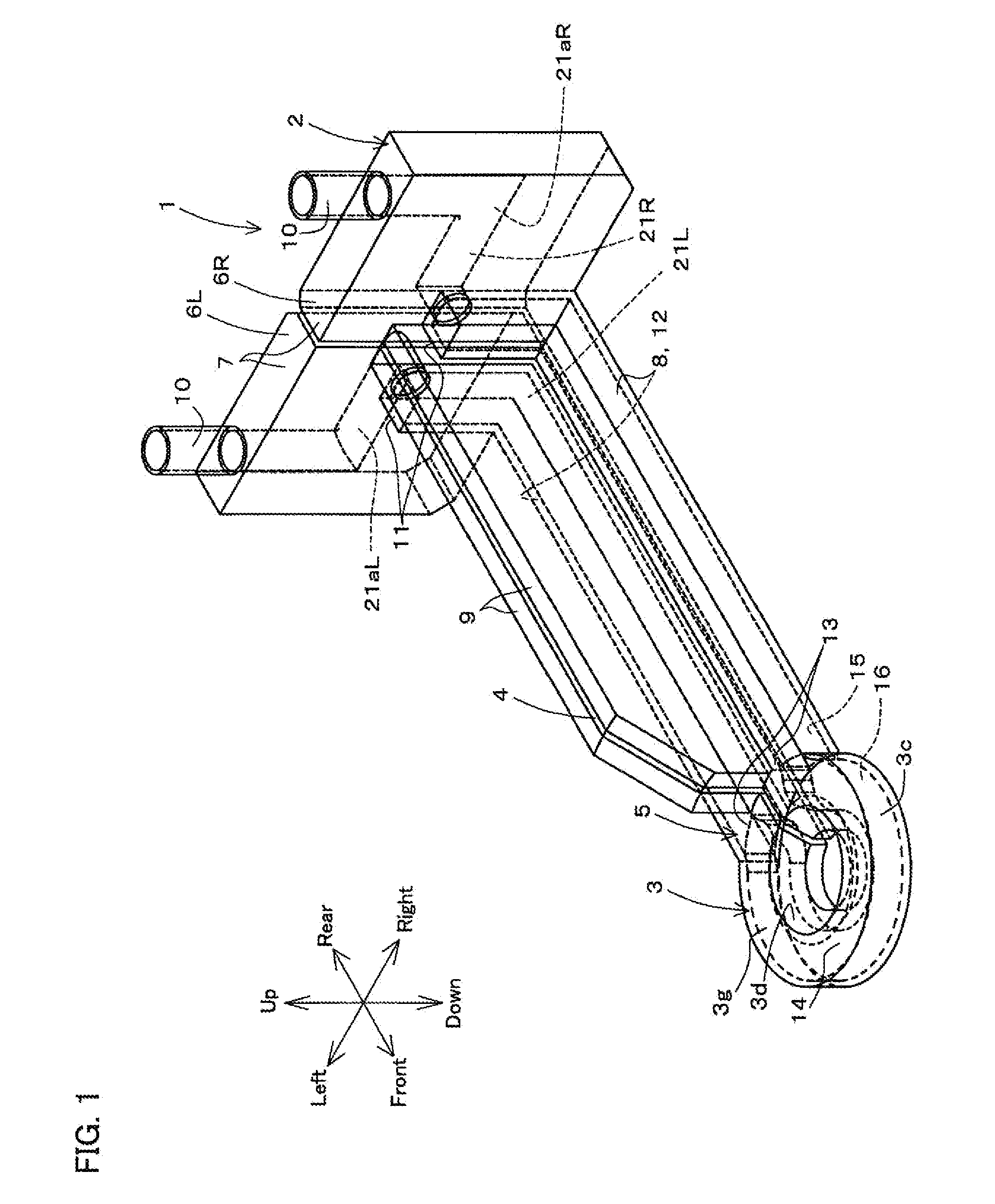
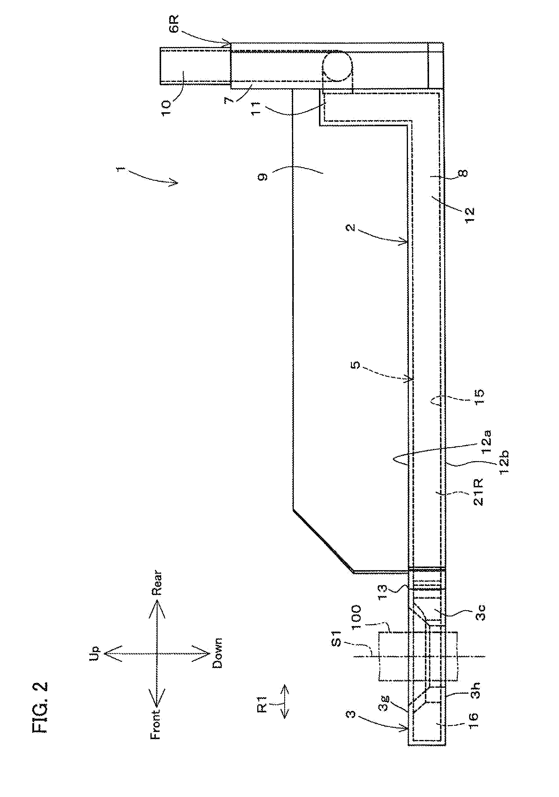
[0070]FIG. 1 is a perspective view of an induction heating coil 1 according to a first embodiment of the present invention. FIG. 2 is a side view of the induction heating coil 1. FIG. 3 is a plan view of the induction heating coil 1. FIG. 4 is a cross-sectional view of the state in which the periphery of a coil section 3 of the induction heating coil 1 is viewed in a plan view. FIG. 5 is a cross-sectional view of the state in which the periphery of the coil section 3 is viewed in a side view. FIG. 6 is an enlarged perspective view of the periphery of the coil section 3 of the induction heating coil 1.

[0071]Note that in the following, “up and down”, “front and rear”, and “right and left” respectively refer to “up and down”, “front and rear”, and “right and left” when a viewer views the induction heating coil 1 in the state of facing the front surface of the induction heating coil 1.

[0072]Referring to FIGS. 1 to 3, the induction heating coil 1 is used for performing heat treatment, su...

second embodiment

[0162]FIG. 13 is a perspective view of an induction heating coil 1A according to a second embodiment of the present invention. FIG. 14 is an enlarged perspective view showing the coil section 3 of the FIG. 13. FIG. 15 is a side view of the coil section 3. FIG. 16 is a plan view of the coil section 3. Note that the following will mainly describe configurations different from those of the first embodiment, and the similar reference numerals are given to the similar configurations as in the first embodiment and descriptions thereof are omitted.

[0163]Referring to FIGS. 13 to 16, the induction heating coil1A includes the power supply section 2, the coil section 3, the insulator 4, a cooling water passage 61, and a second cooling water passage 62. The constituent components of the induction heating coil 1A other than the insulator 4 are formed using the metal additive fabrication method.

[0164]The cooling water passage 61 is provided as a water passage through which cooling water for cooli...


PUM

PropertyMeasurementUnit
Thicknessaaaaaaaaaa
Areaaaaaaaaaaa
Heightaaaaaaaaaa

Abstract

An induction heating coil includes a coil section configured to heat a treatment target by induction, a power supply section configured to supply power to the coil section, and a cooling medium passage that is arranged in the power supply section and the coil section, and is configured to supply a cooling medium to the coil section. The coil section, the power supply section, and the cooling medium passage are formed using a metal additive fabrication method.

Description

CROSS-REFERENCE TO RELATED APPLICATION[0001]This application claims priority to Japanese Patent Application No. 2014-98906. The entire disclosure of Japanese Patent Application No. 2014-98906 is hereby incorporated herein by reference.BACKGROUND OF THE INVENTION[0002]1. Field of the Invention[0003]The present invention relates to an induction heating coil, and a method for manufacturing the induction heating coil.[0004]2. Description of Related Art[0005]An induction heating coil may be used in order to, for example, subject metal machine parts such as a shaft to a heat treatment by high frequency induction heating (see JP 2013-136819A, for example). An induction heating coil disclosed in JP 2013-136819A includes a circular ring-shaped coil section which is constituted to surround a shaft serving as a treatment target. A large current is supplied to the coil section to operate it to carry out the induction heating.[0006]This high electrical current is supplied to the coil section via...

Claims


Application Information

Patent Timeline
IPC IPC(8): H05B6/42B23K26/34H05B6/04
CPCH05B6/42H05B6/04B33Y80/00B33Y10/00B23K26/345B23K26/342B23K26/34Y02P10/25B23K26/346
Inventor YAMAMOTO, RYOSUKENAKATA, AYAKAFUJIYAMA, NORIHIDE
Owner KOYO THERMO SYST CO LTD
Why Eureka
Try Eureka