Particle therapy apparatus

a technology of particle beams and spherical tubes, applied in the direction of accelerators, radiation therapy, therapy, etc., can solve the problem of displaced particle beam trajectory from the designed trajectory, and achieve the effect of reducing the installation space from becoming excessively large, accurate and appropriate doses

Inactive Publication Date: 2015-11-19
MITSUBISHI ELECTRIC CORP
View PDF4 Cites 20 Cited by
  • Summary
  • Abstract
  • Description
  • Claims
  • Application Information

AI Technical Summary

Benefits of technology

[0010]In a particle therapy apparatus according to the present invention, the straight distance is secured by use of the space inside a rotating gantry; therefore, there can be obtained a particle therapy apparatus that can suppress the installation space from becoming excessively large and can deliver an accurate and appropriate dose.

Problems solved by technology

For that purpose, it is required to correctly maintain the trajectory of a particle beam; however, due to installation errors of apparatuses in the transport path between a radiation source and an irradiation device and an error in the magnetic-field intensity or the like, the particle-beam trajectory may be displaced from the designed trajectory.

Method used


Image

  • Particle therapy apparatus
  • Particle therapy apparatus
  • Particle therapy apparatus

Examples


embodiment 1

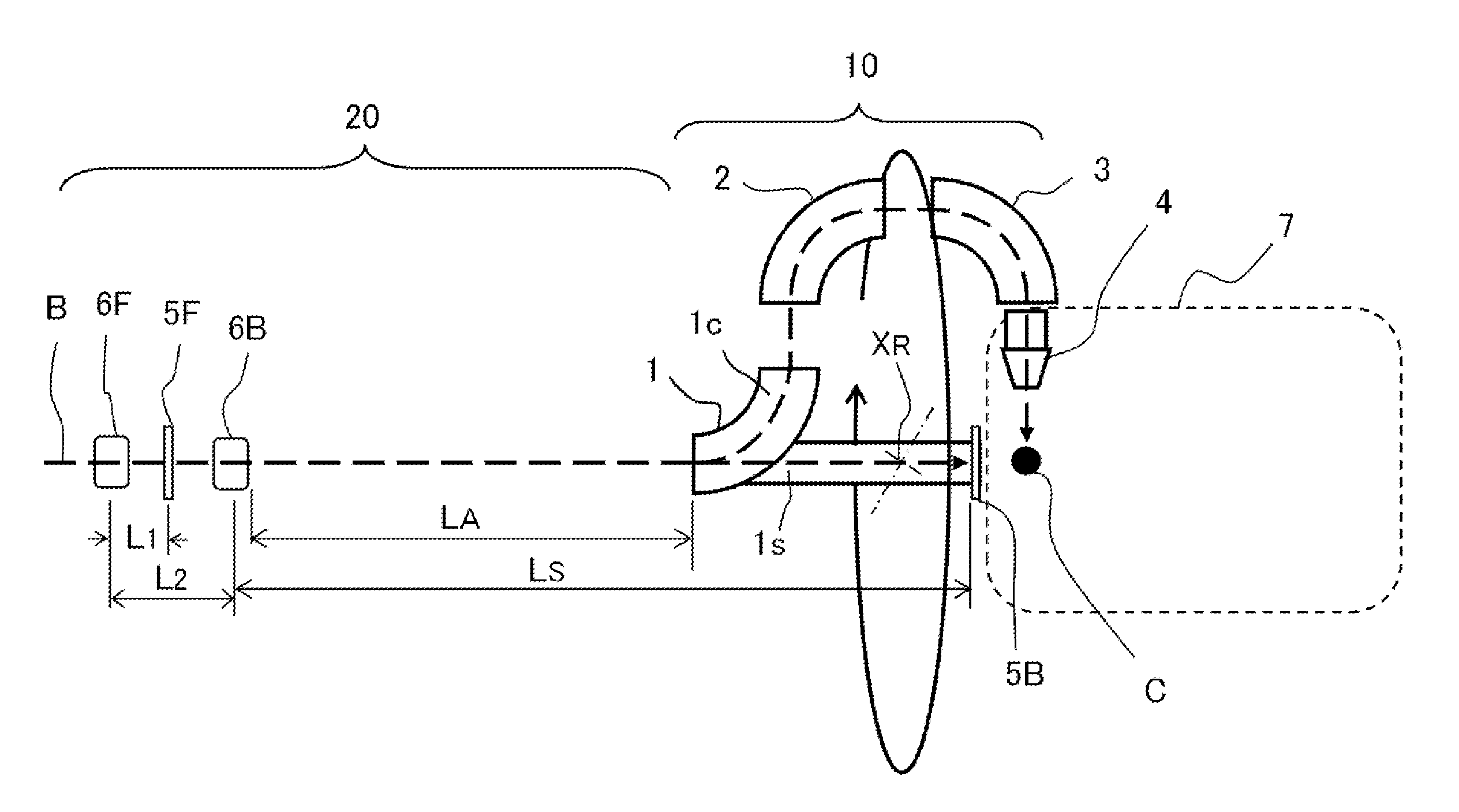
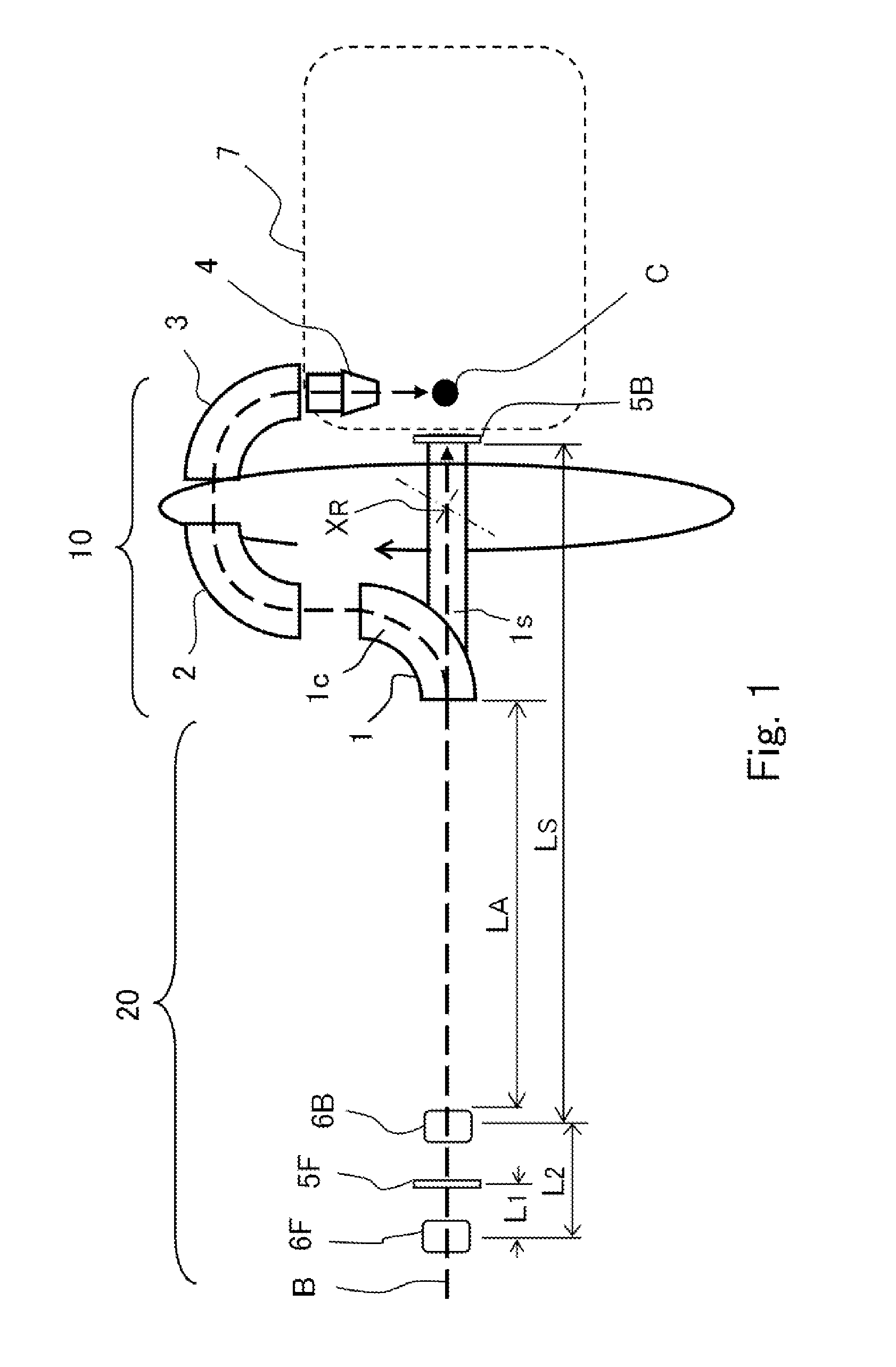
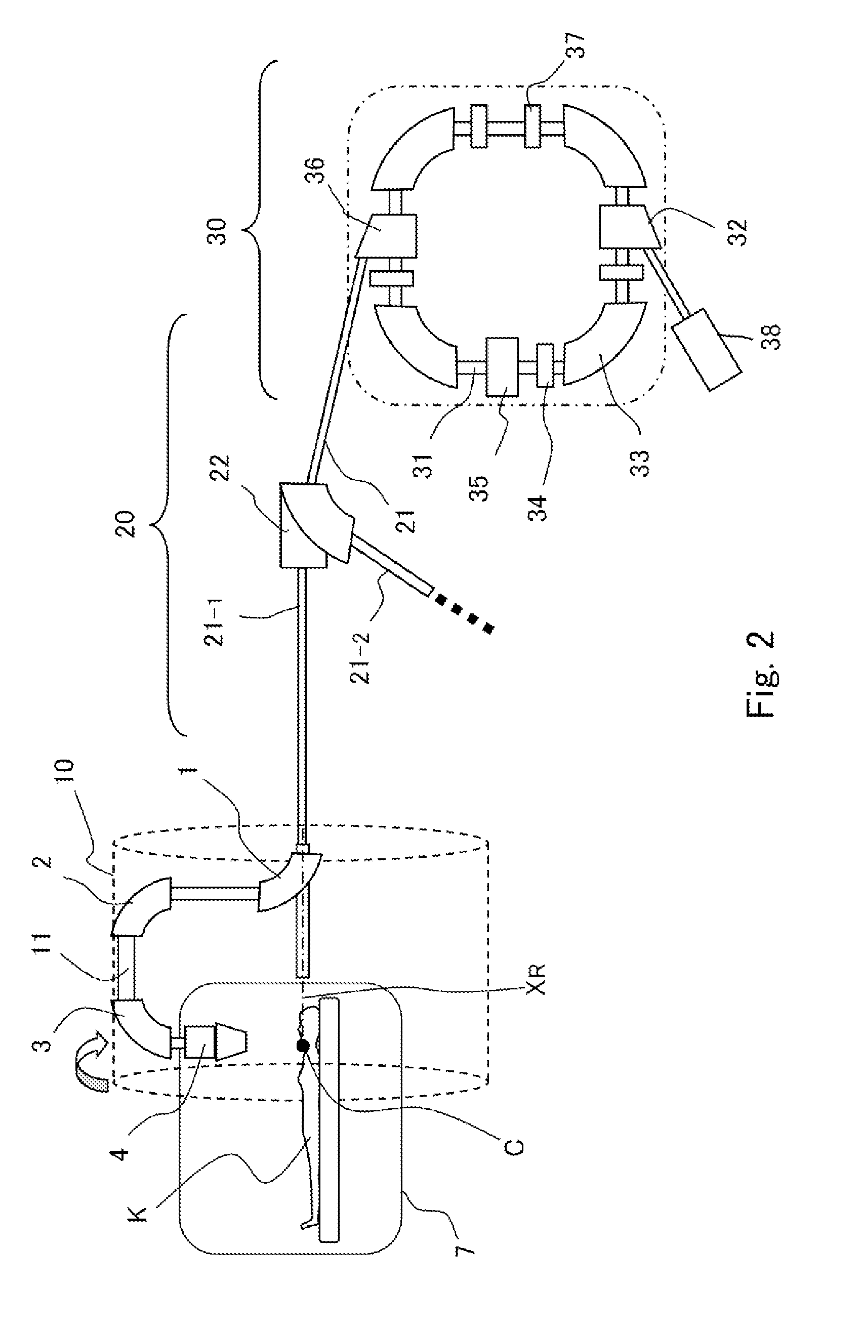
[0020]The configuration of a particle therapy apparatus according to Embodiment 1 of the present invention will be explained below. FIGS. 1 and 2 are views for explaining the configuration of a particle therapy apparatus according to Embodiment 1 of the present invention; FIG. 1 is a view illustrating the arrangement of major devices in the vicinity of a rotating gantry in the particle therapy apparatus, and FIG. 1 is a view for explaining the configuration of a device for correcting the trajectory of a particle beam to be supplied to the rotating gantry; FIG. 2 is a view for explaining the overall configuration of the particle therapy apparatus.

[0021]The characteristics of the particle therapy apparatus according to Embodiment 1 of the present invention are the configurations of deflection electromagnets, of the rotating gantry, that are to correct the trajectory of a particle beam to be supplied to the rotating gantry and the arrangement of beam position sensors for correcting the...

embodiment 2

[0047]In Embodiment 2, the arrangement order, in Embodiment 1, of the beam position sensors and the steering electromagnets included in the trajectory correcting devices is partially changed. FIG. 3 is to explain a particle therapy apparatus according to Embodiment 2; FIG. 3 is a view illustrating the arrangement of major devices in the vicinity of a rotating gantry in the particle therapy apparatus, and is to explain the configuration of a device for correcting the trajectory of a particle beam to be supplied to the rotating gantry. In FIG. 3, constituent elements that are the same as those in Embodiment 1 are designated by the same reference characters, and the detailed explanations therefor will be omitted. FIG. 2 explained in Embodiment 1 is also utilized in Embodiments after and including Embodiment 2.

[0048]As illustrated in FIG. 3, also in Embodiment 2, the first steering electromagnet 6F and the second position sensor 5B are arranged at the uppermost stream side and at the mo...

embodiment 3

[0055]In each of Embodiments 1 and 2, an example had been described in which the straight portion up to the second position sensor is extended to the front of an irradiation chamber. In Embodiment 3 and Embodiments 4 and 5 to be described later, the straight portion up to the second position sensor is extended to the inside of the irradiation chamber. FIG. 4 is to explain a particle therapy apparatus according to Embodiment 3; FIG. 4 is a view illustrating the arrangement of major devices in the vicinity of a rotating gantry in the particle therapy apparatus, and is to explain the configuration of a device for correcting the trajectory of the particle beam B to be supplied to the rotating gantry. In FIG. 4, constituent elements that are the same as those in Embodiment 1 or Embodiment 2 are designated by the same reference characters, and the detailed explanations therefor will be omitted. FIG. 2 explained in Embodiment 1 is also utilized in Embodiment 3 and Embodiments 4 and 5, desc...


PUM


Abstract

A particle therapy apparatus has a rotating gantry configured in such a way that an irradiation device is rotated around a rotation axis and a particle beam is irradiated onto an irradiation subject; the rotating gantry is provided with an entrance-side deflection electromagnet having a deflection path for radially deflecting the particle beam supplied along the rotation axis so as to guide the particle beam to the irradiation device and a straight path that is switchable with the deflection path and is for making the supplied particle beam travel in a straight manner; there are provided trajectory correcting devices having two position sensors that are arranged along the rotation axis so as to flank the entrance-side deflection electromagnet.

Description

TECHNICAL FIELD[0001]The present invention relates to a particle therapy apparatus to be utilized in a cancer treatment or the like and particularly to a particle therapy apparatus in which multi-port irradiation is performed by use of a rotating gantry.BACKGROUND ART[0002]In a particle beam therapy, the therapy is implemented by irradiating a charged particle beam (particle beam) onto a diseased site, which is a therapy subject, so as to cause a damage in the tissues of the diseased site. In this situation, in order to deliver a sufficient dose to the tissues of the diseased site without causing damage to the peripheral tissues thereof, it is required to appropriately control an irradiation dose and an irradiation coverage (irradiation field). For that purpose, it is required to correctly maintain the trajectory of a particle beam; however, due to installation errors of apparatuses in the transport path between a radiation source and an irradiation device and an error in the magnet...

Claims


Application Information

Patent Timeline
Patent Type & Authority Applications(United States)
IPC IPC(8): A61N5/10
CPCA61N5/1081A61N2005/1087H05H7/04H05H2007/008H05H2007/046H05H2007/048
Inventor ODAWARA, SHUHEIHARADA, HISASHIIKEDA, MASAHIROSUGAHARA, KENGO
Owner MITSUBISHI ELECTRIC CORP
Why Eureka
Try Eureka