
Radar energy absorbing deformable low drag vortex generator

a generator and low drag technology, applied in the direction of electrographic process, air-flow influencer, instruments, etc., can solve the problems of radar cross-section spike generation, inability to conform to curved surfaces, etc., to reduce vibration, noise and buffet, the effect of reducing drag

Active Publication Date: 2015-11-19
UNIVERSITY OF KANSAS
View PDF4 Cites 16 Cited by
  • Summary
  • Abstract
  • Description
  • Claims
  • Application Information

AI Technical Summary

Benefits of technology

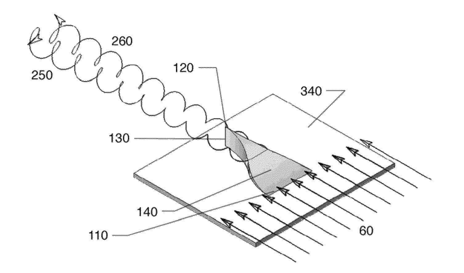
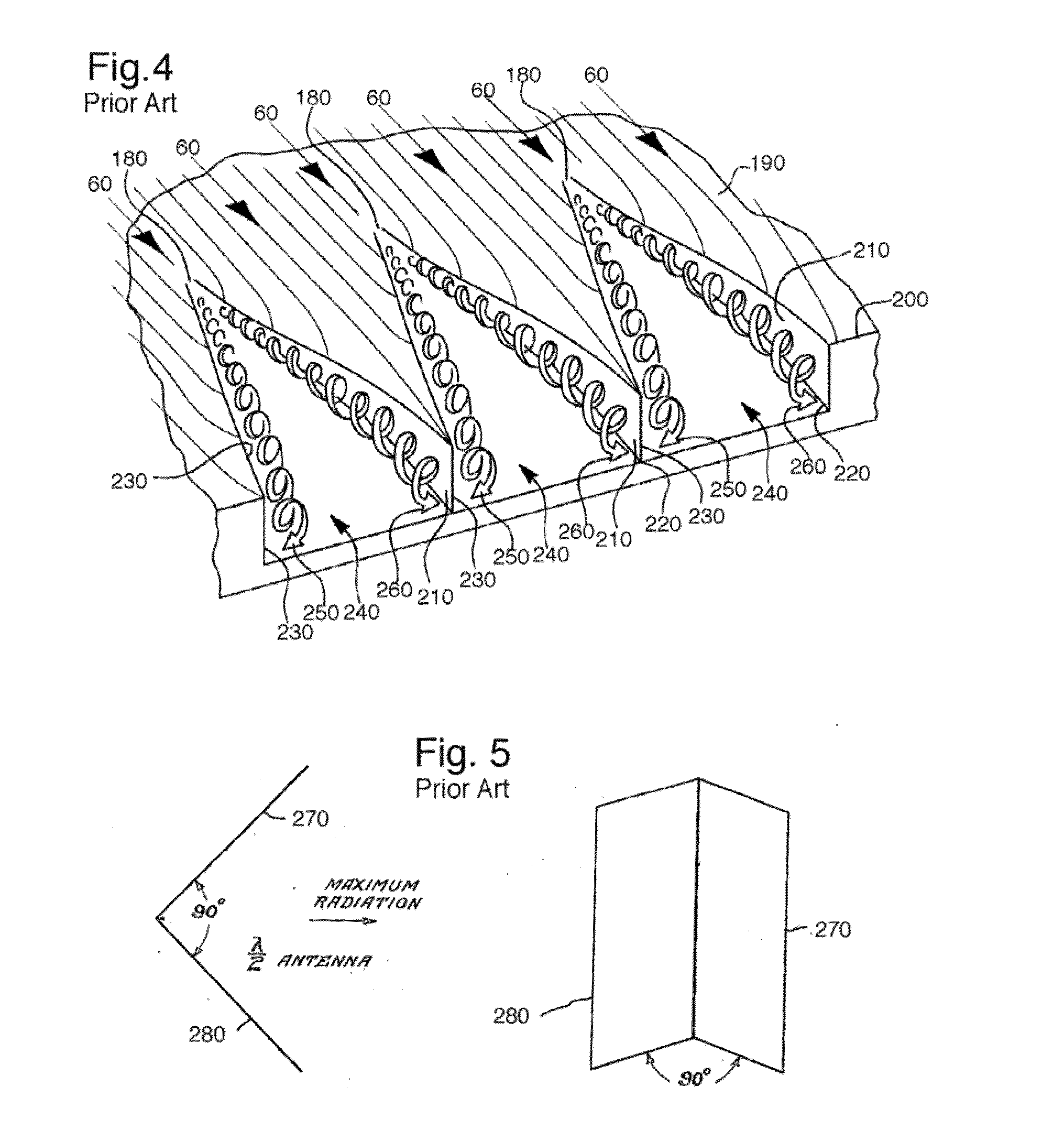
The patent describes a new device called the Radar energy Absorbing Low Drag Vortex Generator (RAD-LDVG) that can be easily installed on aircraft to reduce drag, mitigate vibration, noise, and buffet, and increase maximum aircraft lift capability. The device features a ramp-shape that forces the low energy boundary layer to go up the ramp and spill over a pair of angled sides, which are then wrapped up into a single or pair of counter-rotating steamwise vortices. The device can conform to aircraft surface features and reduce radar cross-section. It is flexible and can be shaped to the surface curvature during installation. The device will inherently shrink in height as it is exposed to increased dynamic pressure from oncoming airflow at greater flight speeds and will increase vortex generator effectiveness during low dynamic pressure flight phases.

Problems solved by technology

Although conventional rigid VGs do generate vortical aerodynamic structures, two major problems are often experienced: i.) the inability to conform to curved surfaces, ii.) the generation of radar cross-section spikes produced by the VGs themselves.

Method used


Image

  • Radar energy absorbing deformable low drag vortex generator
  • Radar energy absorbing deformable low drag vortex generator
  • Radar energy absorbing deformable low drag vortex generator

Examples


Embodiment Construction

[0051]This application claims priority to and the benefit of U.S. Provisional Patent Application Ser. No. 61 / 747,888 entitled, RADAR ABSORBING DEFORMABLE LOW DRAG VORTEX GENERATOR, filed Dec. 31, 2012, which is incorporated by reference herein in its entirety.

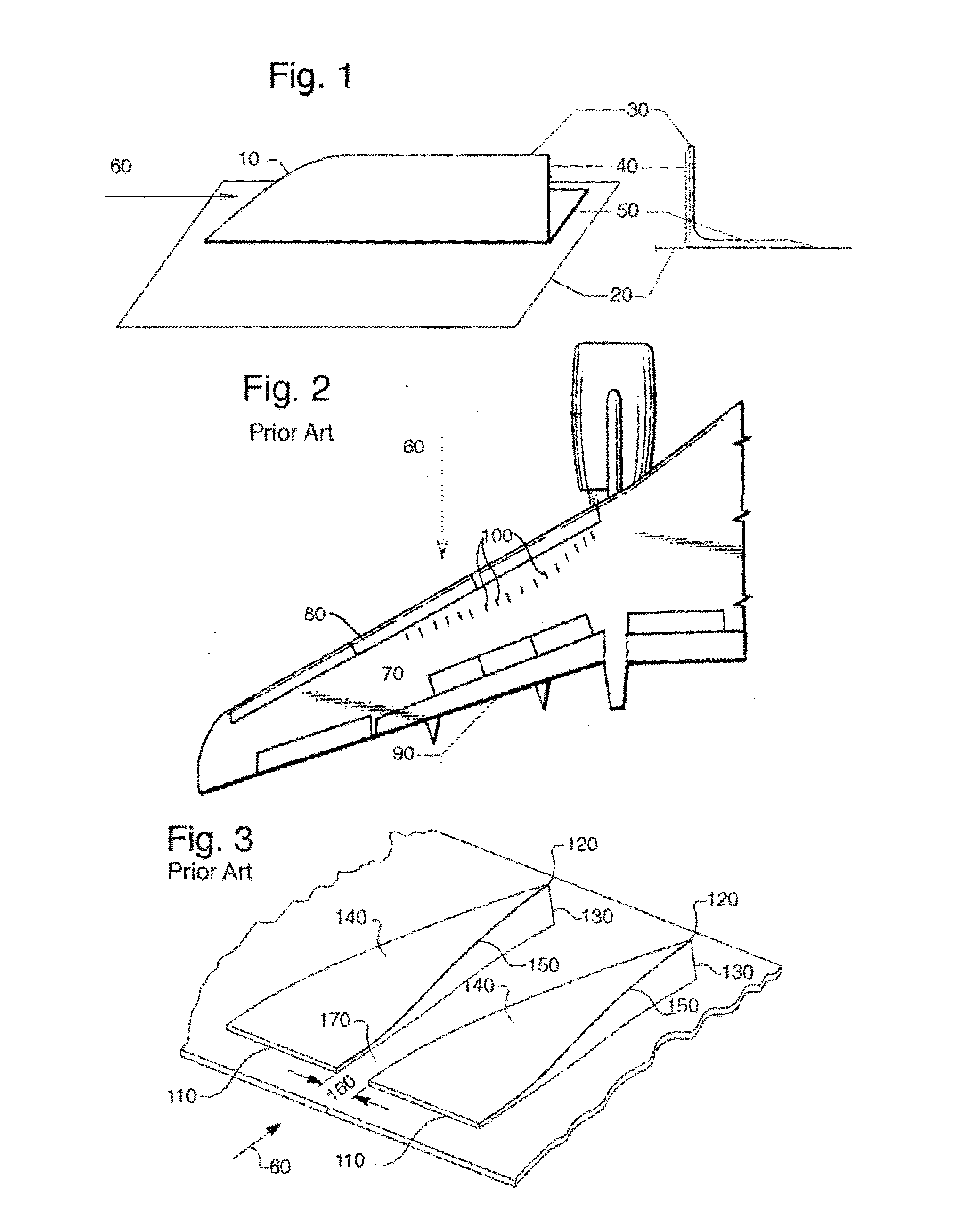
[0052]Starting with the Bf-110 Zerstorer of 1936, vortex generators of the configuration shown in FIG. 1 have been regularly used on a variety of aircraft for a variety of purposes. This conventional, rigid VG (10) has a vertical portion which is approximately normal to the aircraft surface (20) and either bonded, riveted or screwed in place. The upper edge (30) is set at a finite cant angle against the oncoming airflow and will peel a vortical structure as it separates at that edge. The vertical riser (40) is most often made from either aluminum or steel and integrated to a structural foot (50). The height of the rigid VG is typically set in accordance with its intended use and local boundary layer height. Clearly, prior art t...


PUM


Abstract

A family of Radar energy Absorbing Deformable Low Drag Vortex Generators (RAD-LDVG) is described herein. This family of devices are fabricated in such a way that it can conform to aircraft surface features while reducing radar returns from structural details. Vortex generators (VGs) are typically used to reattach or smooth gross flowfields over aircraft surfaces. By doing so, an airfoil or wing can maintain attached flow at higher angles of attack and / or higher lift coefficients than one without the VGs. These devices are also used to reattach and / or smooth flows that encounter crossflow-induced instabilities and / or adverse pressure gradients on the upper surfaces of wings or near aircraft boattails. Other uses include reduction of buffet, vibration, flutter, cavity resonance or general bluff-body pressure drag reduction. Although conventional rigid VGs do generate vortical aerodynamic structures, two major problems are often experienced: i.) the inability to conform to curved surfaces, ii.) the generation of radar cross-section spikes produced by the VGs themselves.

Description

CROSS REFERENCE[0001]This application claims priority to and the benefit of U.S. Provisional Patent Application Ser. No. 61 / 747,888 entitled, RADAR ABSORBING DEFORMABLE LOW DRAG VORTEX GENERATOR, filed Dec. 31, 2012, which is incorporated by reference herein in its entirety.BACKGROUND OF THE INVENTION[0002]Field The Radar energy Absorbing Low Drag Vortex Generator (RAD-LDVG) relates to a class of devices which produce vortices over external or internal aerodynamic and / or hydrodynamic surfaces.[0003]Background Art Vortex generators (VGs) come in a wide variety of shapes and sizes, but are used to increase maximum lift coefficients, and / or reattach flows which would separate, and / or smooth unstable flows over lifting surfaces, stabilizers, high lift devices or flight control mechanisms. Some of the first mentions of devices which were intentionally designed to produce aerodynamic vortices were described in the 1930's. U.S. Pat. No. 1,994,045 describes an aircraft with a plurality of r...

Claims


Application Information

Patent Timeline
IPC IPC(8): B64C21/02F15D1/00H01Q17/00
CPCB64C21/02F15D1/003H01Q17/004H01Q17/008B64C23/06F15D1/004Y02T50/10G03G13/26G03G13/283
Inventor BARRETT, RONALD M.
Owner UNIVERSITY OF KANSAS
Learn More