Gas Chromatograph System Employing Hydrogen Carrier Gas

a hydrogen carrier gas and gas chromatograph technology, applied in the field of gas chromatography, can solve the problems of non-reproducible quantitation, less chemically reactive than nitrogen, helium or argon, and detrimental to the stationary phase chemistry of the column, and achieve the effect of facilitating the separation of the transferred sample components

Active Publication Date: 2015-11-19
THERMO FINNIGAN
View PDF9 Cites 5 Cited by
  • Summary
  • Abstract
  • Description
  • Claims
  • Application Information

AI Technical Summary

Benefits of technology

[0017]In a second aspect of the present teachings, a gas chromatography (GC) system is provided, the system comprising: a sample injector comprising a heater and a gas inlet port; a gas inlet line fluidically coupled to the gas inlet line operable to supply an inert gas to the sample injector from a source of inert gas; a GC analytical column fluidically coupled to the sample injector and configured to receive a volatilized sample and the supplied gas from the sample injector; a tee coupler fluidically coupled between the sample injector and the GC analytical column; a source of hydrogen gas; a hydrogen supply line fluidically coupled between the tee coupler and the source of hydrogen gas; and a calibrated flow restrictor and a shutoff valve fluidically coupled between a first and a second portion of the hydrogen supply line; wherein the shutoff valve is configured to supply a flow of hydrogen carrier gas from the source of hydrogen gas to the GC analytical column only during chromatographic separation of sample components within the GC analytical column and during transport of the separated components to a detector and the calibrated flow restrictor is configured to limit a flow rate of the hydrogen carrier gas to within a safety limit. In various embodiments, the source of hydrogen may comprise a hydrogen generator apparatus. In various embodiments, the calibrated flow restrictor may be configured to limit the flow rate of the hydrogen carrier gas to less than 5 standard cubic centimeters per minute. In various embodiments, the calibrated flow restrictor may be configured such that the flow of hydrogen carrier gas to the GC analytical column is greater than a flow rate that can be accommodated by the column and such that a portion of the hydrogen carrier gas mixes with a purge gas that flows through the sample injector.
[0018]In a third aspect, there is provided a method for operating a gas chromatography (GC) system comprising a sample injector and a GC analytical column, the method comprising: (i) causing an inert transfer gas to flow into the sample injector; (ii) introducing a liquid sample into the sample injector such that components of the sample are volatilized therein and transferred into the GC analytical column under the flow of inert transfer gas; (iii) causing hydrogen carrier gas to flow into the GC analytical column so as to facilitate separation of the transferred sample components within the GC analytical column and so as to transport the separated components to a detector; and (iv) ceasing the flow of hydrogen carrier gas. In various embodiments, the steps (i) through (iv) may be repeated, wherein another liquid sample is introduced into the sample injector during the repeated step (ii). In various embodiments, the step (iii) of causing hydrogen carrier gas to flow into the GC analytical column may comprise causing the hydrogen carrier gas to flow into and through the sample injector into the GC analytical column. In some of such embodiments, the step (iii) may be performed by operation of a gas selection valve that is fluidically coupled between the sample injector and each of an inert gas source and a hydrogen gas source. In various alternative embodiments, the step (iii) of causing hydrogen carrier gas to flow into the GC analytical column may comprise causing the hydrogen carrier gas to flow from a hydrogen gas source into a tee coupler fluidically coupled between the sample injector and the GC analytical column and, additionally, the hydrogen carrier gas may be caused to flow at a flow rate that is greater than a maximum flow rate that can be accommodated by the GC analytical column such that a portion of the hydrogen carrier gas mixes with a purge gas that flows through the sample injector. In some of such embodiments, the method may further comprise: (v) causing a purge gas to flow through the GC analytical column during an idle time when no samples flowing through or are being transferred into the GC analytical column, wherein the purge gas is introduced through the tee coupler.

Problems solved by technology

Unfortunately, while hydrogen can achieve high levels of separation power per unit time, it has the disadvantage of being more chemically reactive than nitrogen, helium or argon.
Additionally, the amount of conversion can vary depending on the activity of the injection port liner, rendering quantitation which is non-reproducible.
This can have a detrimental effect on the column stationary phase chemistry.
These precautions may include a costly hydrogen sensor capable of disabling power to the system in the event of a large hydrogen leak.
The indirect control of flow using pressure as described above can result in a relatively unbounded flow of carrier gas if the column should break near the point where the column enters the injector.
This presents a potential safety hazard associated with the conventional system 25 if hydrogen is utilized as the carrier gas.

Method used


Image

  • Gas Chromatograph System Employing Hydrogen Carrier Gas
  • Gas Chromatograph System Employing Hydrogen Carrier Gas
  • Gas Chromatograph System Employing Hydrogen Carrier Gas

Examples


Embodiment Construction

[0025]This disclosure describes improved gas chromatograph systems and methods for operating gas chromatograph systems. The following description is presented to enable any person skilled in the art to make and use the invention, and is provided in the context of a particular application and its requirements. Various modifications to the described embodiments will be readily apparent to those skilled in the art and the generic principles herein may be applied to other embodiments. Thus, the present invention is not intended to be limited to the embodiments and examples shown but is to be accorded the widest possible scope in accordance with the features and principles shown and described. To more particularly appreciate the features of the present invention, the reader is referred to FIGS. 1 through 5 in conjunction with the following description.

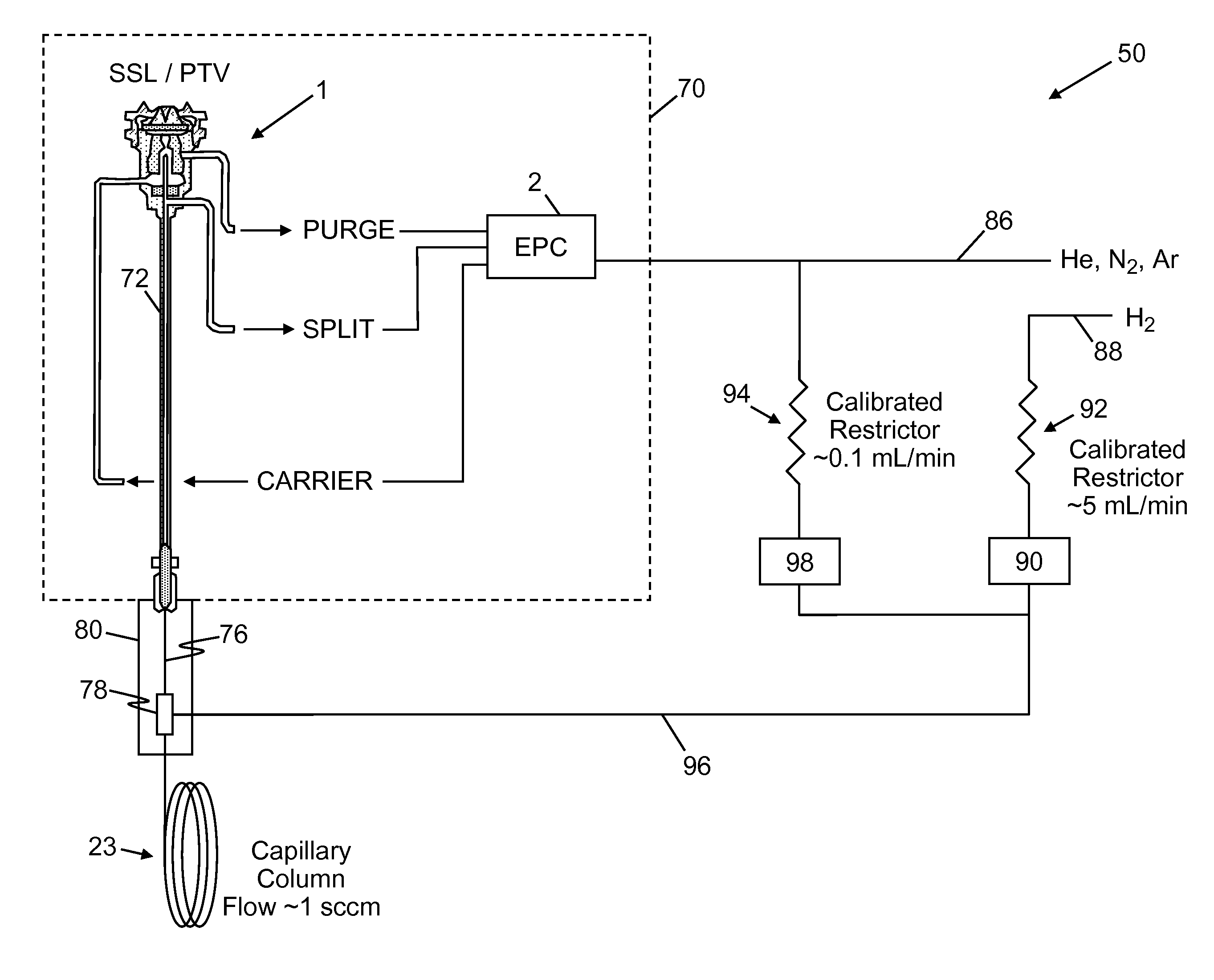
[0026]FIG. 3 illustrates a first gas supply and exhaust system 30 for a gas chromatograph in accordance the present teachings. The injecto...


PUM

PropertyMeasurementUnit
lengthaaaaaaaaaa
temperatureaaaaaaaaaa

Abstract

An injection port for a gas chromatograph (GC) is operated such that, during an injection sequence, an inert gas is used for sample transfer to the analytical column while hydrogen is subsequently utilized for the majority of the analytical separation. This allows for a high degree of chromatographic efficiency, while also reducing unwanted chemical reactions involving hydrogen and/or reactive solvents in a hot injection port. Certain embodiments also provide an increased margin of safety when using hydrogen, since the total flow may be limited such that the concentration of hydrogen in the GC oven never exceeds a safety limit, such as the lower explosive limit.

Description

CROSS REFERENCE TO RELATED APPLICATION[0001]This application claims, under 35 U.S.C. §119(a), the benefit of the filing date and the right of priority to European application EP 14425056, filed on May 13, 2014.FIELD OF THE INVENTION[0002]This invention relates to gas chromatography and, more particularly, to improved performance and safety when utilizing hydrogen in gas chromatograph injectors and columns.BACKGROUND OF THE INVENTION[0003]Gas chromatographs are well known devices used to separate chemical mixtures. Within a gas chromatograph is an analytical column which generally comprises an elongate fused silica capillary tube coated internally with a cross bonded stationary phase. The column may be from a few tens to a few hundreds of micrometers in diameter and vary in length from a few meters to as many as a hundred meters or so. It is known to use a carrier gas in these columns such as helium, nitrogen, argon or hydrogen in order to allow transport of the separated analytes th...

Claims


Application Information

Patent Timeline
Patent Type & Authority Applications(United States)
IPC IPC(8): G01N30/20
CPCG01N2030/025G01N30/20B01D15/14G01N30/16G01N30/34B01D53/025
Inventor MCCAULEY, EDWARD B.PONCIROLI, FRANCOMAGNI, PAOLO
Owner THERMO FINNIGAN
Why Eureka
Try Eureka