
Matter-wave gravimeter with microwave separation at the magic field

a gravimeter and magnetic field technology, applied in the field of gravity meters using matter waves, can solve the problems of limited stability of the latter

Active Publication Date: 2015-11-19
THALES SA
View PDF1 Cites 4 Cited by
  • Summary
  • Abstract
  • Description
  • Claims
  • Application Information

AI Technical Summary

Benefits of technology

The invention is a new type of gravimeter that can measure local gravitational fields accurately, even in the presence of other magnetic fields. It uses a special technique called a "contaminated state" to adjust the magnetostatic field to account for these other fields. The gravimeter uses a chip with a measurement axis and a microwave field to trap a cloud of ultra-cold atoms. The atoms are then separated into two wave packets, and the phase-shift caused by the separation is measured using a microwave field and a radiofrequency field. The difference in energy between two internal states of the atoms is used to determine the local gravitational field. The gravimeter also includes calibration means to determine the "magic" magnetostatic field, which is independent of fluctuations in the field. The atoms used are rubidium 87, and the levels are coupled using microwave fields. The separation distance of the atoms is about 20 microns. The invention solves the problem of accurately measuring gravitational fields in the presence of other magnetic fields.

Problems solved by technology

The uncertainty in the measurement of g according to this principle notably depends on the uncertainty in the scale factor K. The stability of the latter is limited in particular by the stability of the distance s between the two wave packets during the measurement.

Method used


Image

  • Matter-wave gravimeter with microwave separation at the magic field
  • Matter-wave gravimeter with microwave separation at the magic field
  • Matter-wave gravimeter with microwave separation at the magic field

Examples


Embodiment Construction

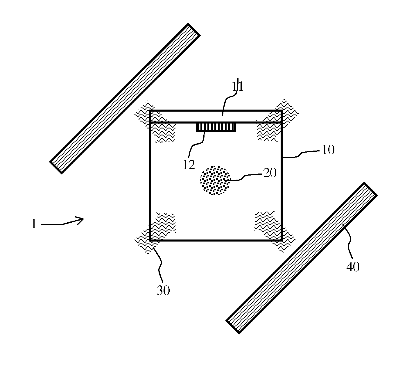
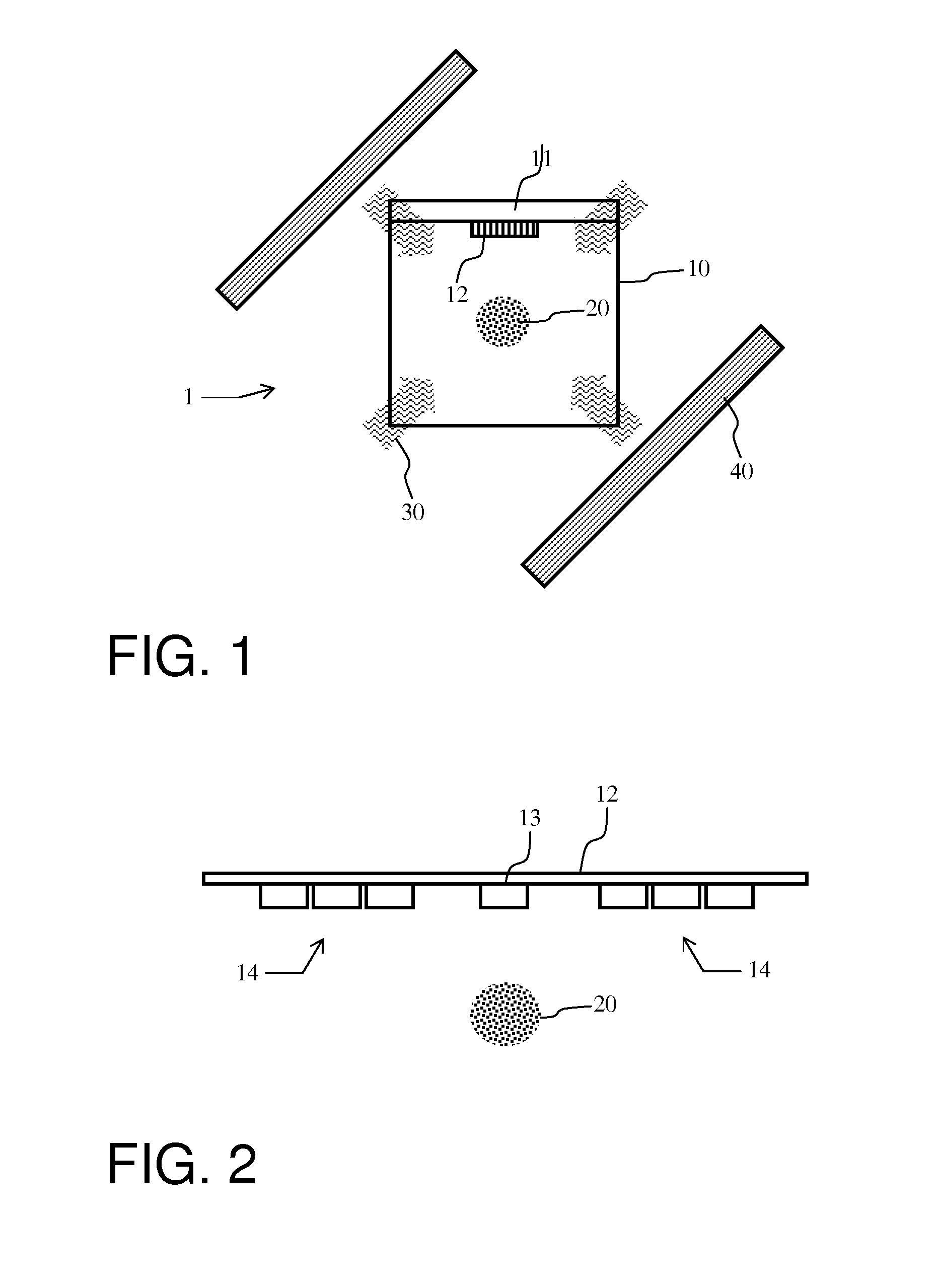
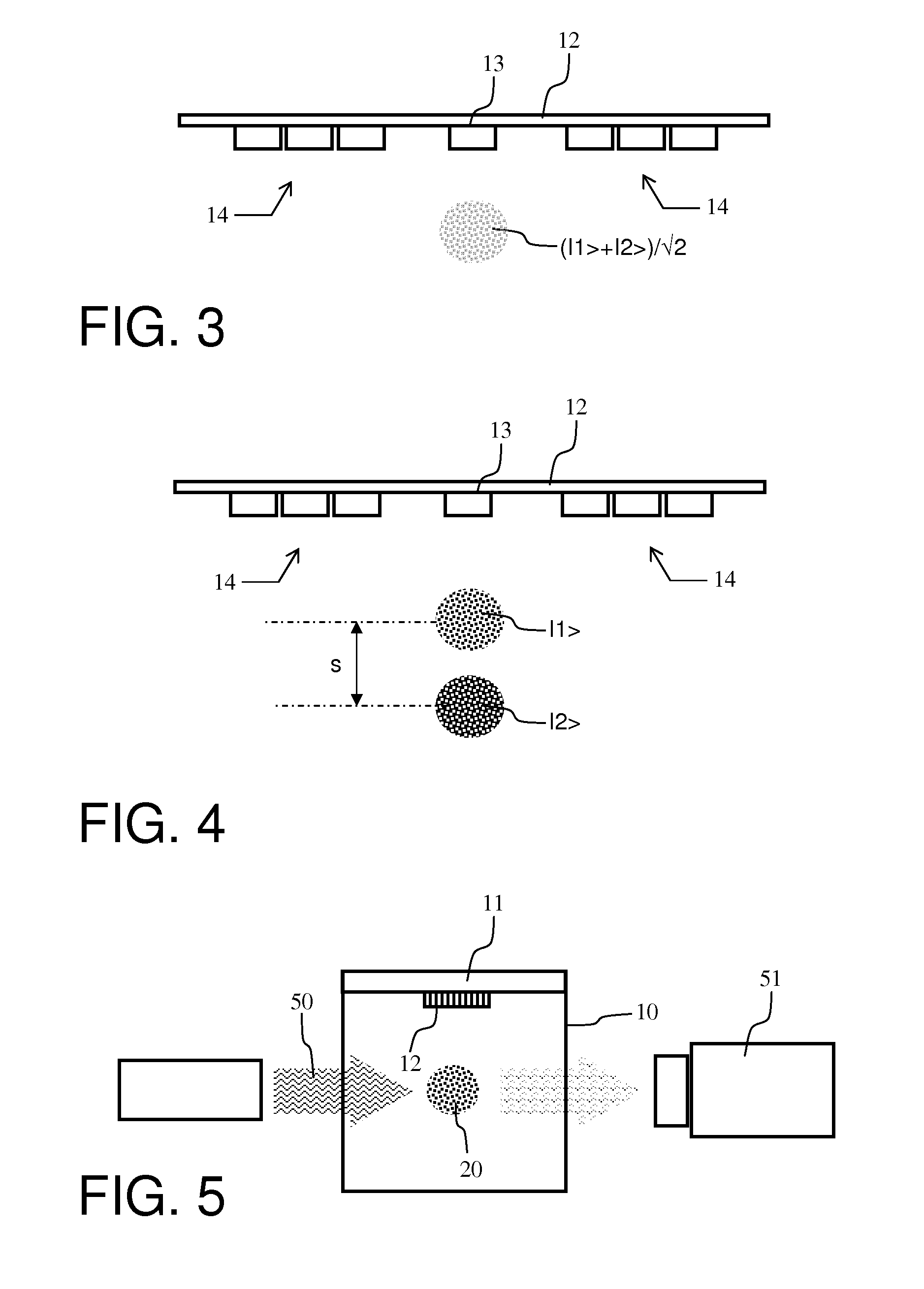
[0045]The architecture of a gravimeter 1 according to the invention is shown on the face view in FIG. 1. The central part is composed of a vacuum vessel 10 all the walls of which are transparent, with the possible exception of the top side 11 which is composed of a chip 12 onto which conducting wires have been deposited.

[0046]The atoms 20, initially in the gaseous phase at the ambient temperature in the cell, are trapped and cooled by means of six laser beams 30 disposed symmetrically two by two on three perpendicular axes in pairs combined with a magnetic field gradient generated by external magnetic coils 40. The six laser beams are disposed symmetrically on three perpendicular axes. In FIG. 1, which is a cross-sectional view, only four of the six laser beams are shown represented by arrows, the two missing beams are perpendicular to the plane of the sheet. The assembly of the laser beams and of the magnetic coils is called a three-dimensional magneto-optical trap or “3D MOT”.

[004...


PUM


Abstract

The general field of the invention is that of matter-wave gravimeters. The gravimeter according to the invention comprises at least:means for generating, for capturing and for cooling a cloud of ultra-cold atoms;means of transferring the atoms into a superposition, with equal weights, of a first internal electronic state called state |1>) and of a second internal electronic state called state |2> comprising the application of at least a first microwave field and of a radiofrequency field;means for separating the atoms into two wave packets for a given period of time under the effect of at least a second microwave field, the said separation leading to a phase-shift associated with the local gravitational field;calibration means allowing a “magic” magnetostatic field to be determined for which the difference in energy between the first internal electronic state and the second internal electronic state is independent, to a first order, of the fluctuations of the magnetostatic field.

Description

BACKGROUND TO THE INVENTION[0001]1. Technical Field of the Invention[0002]The field of the invention is that of gravimeters using matter waves which allow gravity measurements to be obtained with a very high precision. The applications cover very broad technical fields going from oil prospection to navigation by terrain correlation.[0003]2. Description of the Prior Art[0004]Generally speaking, gravimeters based on matter waves use atoms in free fall separated by laser pulses of the “Raman” type.[0005]Another possibility for gravimeters using matter waves consists in using atoms pre-cooled by laser to a very low temperature close to zero degrees Kelvin and trapped in the neighbourhood of a substrate or “atomic chip” throughout the detection cycle. An architecture of this type notably has the advantages of being very compact and of a reduced power consumption.[0006]The principle of operation of this latter type of gravimeter consists in trapping the cold atoms in the neighbourhood of ...

Claims


Application Information

Patent Timeline
Patent Type & Authority Applications(United States)
IPC IPC(8): G01V7/02
CPCG01V7/02G01V7/00
Inventor AMMAR, MAHDISCHWARTZ, SYLVAINHUET, LANDRY
Owner THALES SA
Learn More